Method and Apparatus for Producing a Synthetic Semi-Static Tensile Member

a technology of semi-static tensile members and methods, which is applied in mechanical apparatus, rod connections, cables for vehicles/pulleys, etc., can solve the problems of affecting the quality of synthetic filaments, difficult to organize, and the tensile load of moving buckets on the four cables is enormous

Inactive Publication Date: 2017-12-14
CAMPBELL RICHARD V
View PDF1 Cites 5 Cited by
  • Summary
  • Abstract
  • Description
  • Claims
  • Application Information

AI Technical Summary

Problems solved by technology

The filaments are very strong in tension, but they are not very rigid.
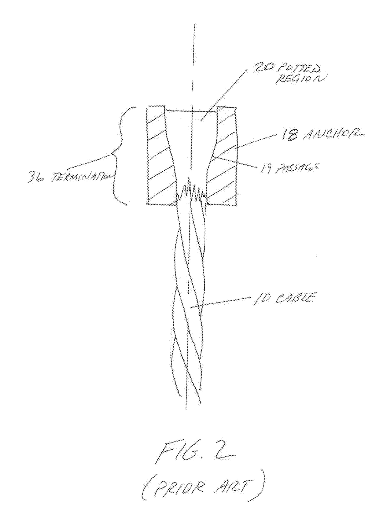
These facts make such synthetic filaments difficult to handle during the process of adding a termination and difficult to organize.
The moving bucket also places enormous tensile loads on the four cables.
As a result, the cable sway and flex.
If one of these cables break, at best the dragline crane will be shut down for an extended period.
At worst the boom may fail catastrophically.
Producing synthetic tensile members with a consistent and predictable overall length is presently a serious industry challenge.
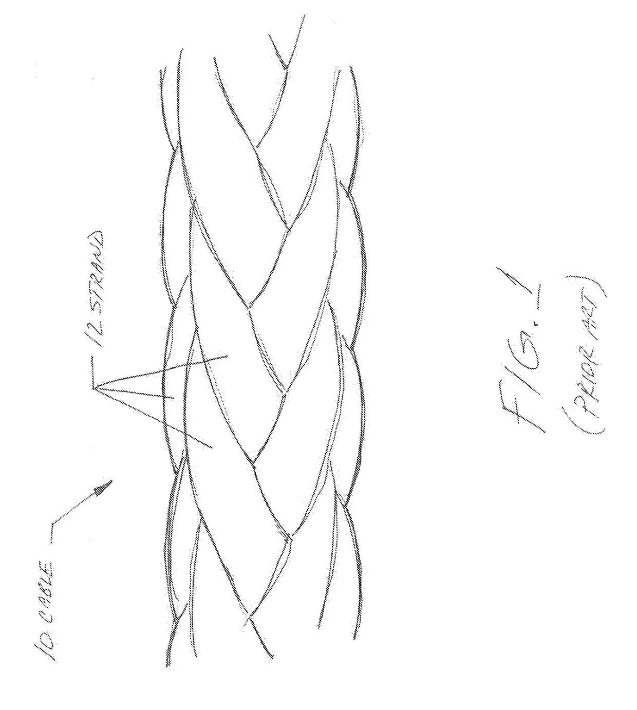
1. The mechanical properties of synthetic filaments vary from batch to batch. While this is true of more traditional materials, the variance is synthetic materials is much greater;
2. Most strands or cables must be created by braiding together thousands to millions of individual synthetic filaments. Two braiding machines may appear to produce a similar result but in fact the properties will vary;
3. There are many steps in fabricating a completed cable assembly using synthetic filaments. Each step introduces additional variations and these variations tend to accumulate;
4. Synthetic filaments must generally be elastically bent and interwoven during the manu...

Method used


Image

  • Method and Apparatus for Producing a Synthetic Semi-Static Tensile Member
  • Method and Apparatus for Producing a Synthetic Semi-Static Tensile Member
  • Method and Apparatus for Producing a Synthetic Semi-Static Tensile Member

Examples


Embodiment Construction

[0067]A cable is a good example of a semi-static tension member. An exemplary cable made according to the present invention will generally have a first termination on its first end and a second termination on its second end. It is important to precondition such a cable after it is made in order to establish a known and stable overall length.

[0068]FIG. 5 shows a synthetic cable assembly created by adding a termination 36 to each end of cable 10. The term “synthetic” in this context should be understood to encompass cables made of 100% synthetic filaments as well as hybrid cables made up of a mix of synthetic filaments and conventional metallic filaments.

[0069]The first termination is connected to static fixture 40 by a pin located at first attachment reference 45. The second termination is attached to loading fixture 38 by a pin located at second attachment reference 47. A predetermined tension profile is then applied through loading fixture 38.

[0070]This tension profile may assume m...


PUM

PropertyMeasurementUnit
Lengthaaaaaaaaaa
Tensile propertiesaaaaaaaaaa
Flexibilityaaaaaaaaaa

Abstract

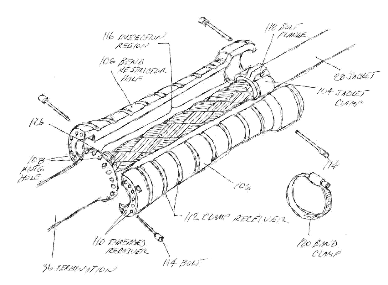
A structure for a semi-static tensile member and a method for producing the semi-static tensile member. A tensile member is prepared by attaching terminations to an assembly of synthetic filaments. The tensile member is then attached to a loading apparatus that subjects the tensile member to a pre-defined loading process. The tensile member is thereby conditioned to a stable length. A bend restricting device is attached to the cable assembly proximate the point where the synthetic strands exit the termination and enter the freely-flexing portion of the cable. The bend restricting device is configured to permit periodic inspection of the cable in the region it covers.

Description

CROSS-REFERENCES TO RELATED APPLICATIONS[0001]This non-provisional patent application claims the benefit of an earlier-filed provisional application. The first provisional application was assigned Ser. No. 62 / 347,121. It listed the same inventor.STATEMENT REGARDING FEDERALLY SPONSORED RESEARCH OR DEVELOPMENT[0002]Not Applicable.MICROFICHE APPENDIX[0003]Not ApplicableBACKGROUND OF THE INVENTION1. Field of the Invention[0004]This invention relates to the field of tensile strength members such as multi-stranded synthetic cables. More specifically, the invention comprises devices and methods for creating a synthetic tensile member having a fixed and stable length where inspection of critical areas is facilitated.2. Description of the Related Art[0005]The term “tensile member” encompasses a very broad range of known devices, including steel rods, braided wire ropes, slings, etc. These devices have for many years been made using steel. For a fixed installation—such as a bridge stay—a rela...

Claims


Application Information

Patent Timeline
IPC IPC(8): F16B7/04D07B1/16D07B5/00D07B1/02
CPCF16B7/0426D07B1/16D07B2201/104D07B1/02D07B5/005F16G11/025F16G11/06F16G11/09
Inventor CAMPBELL, RICHARD V.
Owner CAMPBELL RICHARD V
Why Eureka
Try Eureka