
Pipetting Device, Pipette Tip Coupler, and Pipette Tip: Devices and Methods

a pipette tip and coupler technology, applied in the field of pipetting devices, can solve the problems of microfissure formation, high press force required to pre-press, and the distance to the end of the pipette tip that comes in contact with liquid is not well controlled

Active Publication Date: 2017-12-21
HAMILTON
View PDF5 Cites 11 Cited by
  • Summary
  • Abstract
  • Description
  • Claims
  • Application Information

AI Technical Summary

Benefits of technology

The present patent provides a solution for improving the sealing and performance of pipette tips in a pipette device. The invention is a pipette tip coupler and disposable pipette tip combination that includes a plurality of circumferentially disposed elements or segments engaging a interior working surface of the pipette tip. This results in a pre-stress force that prevents seal deterioration or failure. The coupler also includes a distal elastomeric element that provides a counter axial force to the segments, which ensures a stronger seal when the segments are in a radially and axially interfacing state. The coupler and disposable pipette tip combination allow for precise control of the axial coupled position and targeting of smaller holes, resulting in better accuracy and efficiency in liquid transfer.

Problems solved by technology

Due to the tolerances of the two interfacing components, the distance to the end of the pipette tip that comes in contact with liquid is not well controlled.
In addition, high press forces are required to pre-stress the pipette tip to create the air tight seal.
As a result, microfissures may be formed in the pipette tip which are a cause of leakage.
Moreover, the high press forces upon placement of the pipette tip have the disadvantage that for the release of the pipette tip correspondingly high forces have to be applied.
Notwithstanding, current systems utilizing a stepped coupling stud and a solitary O-ring configuration are problematic when the O-ring becomes compromised because the result is an impairment in the air-tight seal and the performance of the pipette device.

Method used


Image

  • Pipetting Device, Pipette Tip Coupler, and Pipette Tip: Devices and Methods
  • Pipetting Device, Pipette Tip Coupler, and Pipette Tip: Devices and Methods
  • Pipetting Device, Pipette Tip Coupler, and Pipette Tip: Devices and Methods

Examples


Embodiment Construction

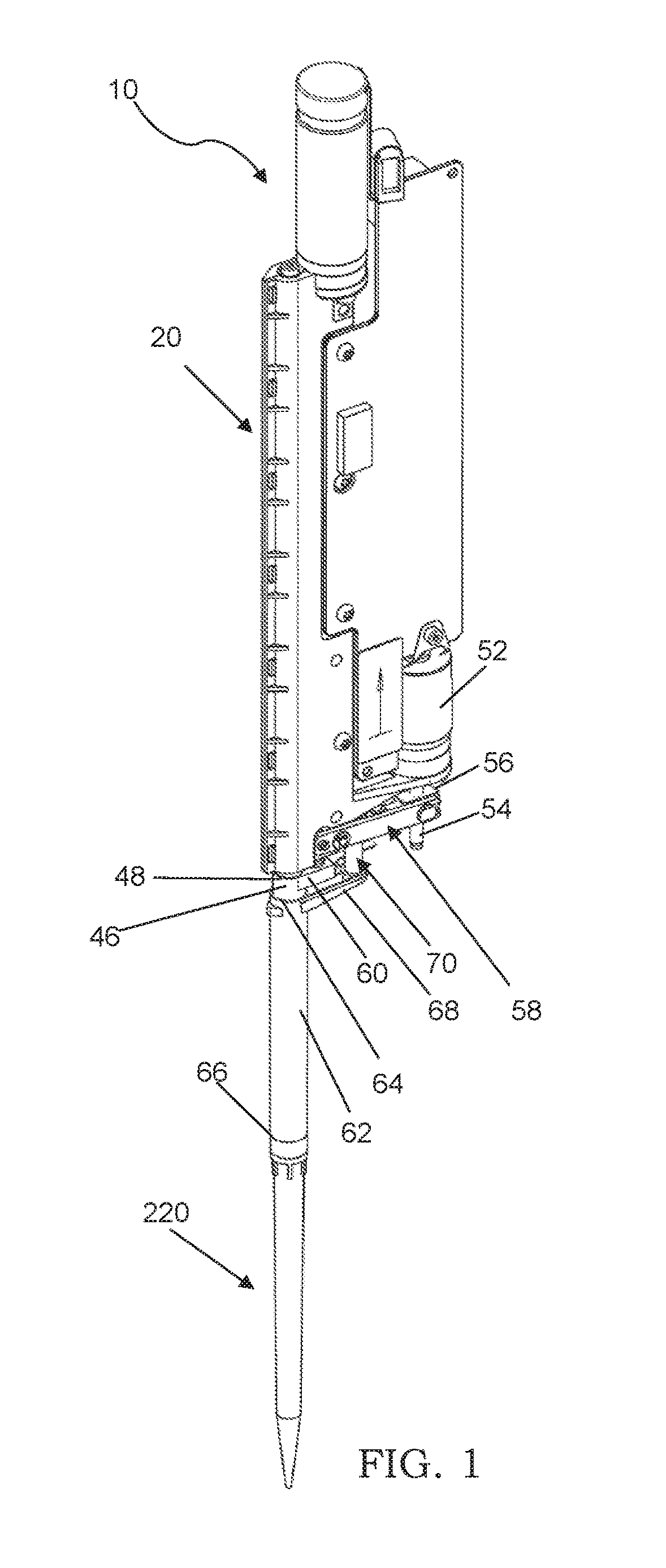
[0078]For the purpose of illustrating the disclosure, there are shown in the drawings embodiments which are presently preferred. These example embodiments will now be described more fully with reference to the accompanying drawings wherein like reference numerals are used to denote like parts or portions throughout the description of the several views of the drawings.

[0079]Pipette Assembly with Expanding Mandrel Collet Coupling and Tip

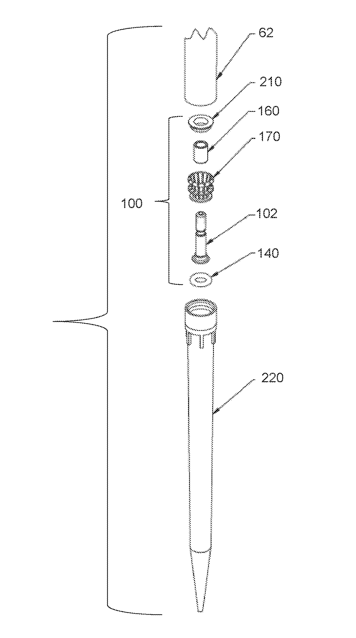
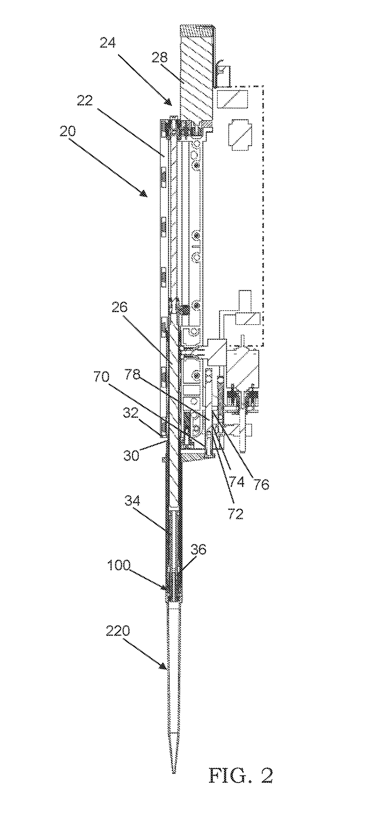
[0080]FIGS. 1 and 2 illustrate an example embodiment of a pipette device assembly 10 comprising an example embodiment of a pipette device 20, an example embodiment of an expanding mandrel collet coupling device 100 or pipette tip coupler, and an example embodiment of a disposable pipette tip 220 removably coupled to the pipette device 20 by way of the expanding mandrel collet coupling device 100.

[0081]Pipette Device 20

[0082]Referring to FIG. 2, the pipette device 20 comprises a body 22 supporting an aspirating and dispensing device 24 comprising a plun...


PUM


Abstract

Pipette assembly comprising a pipette device, a pipette tip, and an expanding mandrel collet coupling device coupling the tip to the pipette device, the coupling device comprising: circumferentially spaced apart segments, an annular base disposed below the segments and comprising a distal portion, an elastomeric element circumscribing the distal portion, and upwardly extending circumferentially spaced apart arms attached at first ends to the annular base and having upper free ends each supporting a different one of the segments configured to expand between a first and a second greater circumference for engaging a first interior working surface of the tip in concurrence with the elastomeric element sealing against a second interior working surface below the first surface and in concurrence with an abutment between a disk exteriorly disposed about a medial portion of the arms and a stepped interior shoulder of the tip disposed between the first and second working surfaces.

Description

CROSS-REFERENCE TO RELATED APPLICATIONS[0001]This application claims priority under 35 USC Section 119(e) to co-pending U.S. Provisional Patent Application No. 62 / 350,302, filed Jun. 15, 2016, the entire disclosure of which is incorporated herein by reference. This application also claims priority under 35 USC Section 119(e) to co-pending U.S. Provisional Patent Application No. 62 / 350,291, filed Jun. 15, 2016, the entire disclosure of which is incorporated herein by reference.FIELD[0002]This disclosure pertains generally to pipetting devices, and more particularly to pipette tip couplers, disposable pipette tips, pipette tip and coupler combinations, and coupling and decoupling methods of at least one disposable pipette tip to or from at least one pipette tip coupler operatively carried by a pipette device.BACKGROUND[0003]Pipette devices are used in a multitude of industries for the transfer of liquids to conduct experimental analysis. As such, to provide control within the experime...

Claims


Application Information

Patent Timeline
Patent Type & Authority Applications(United States)
IPC IPC(8): B01L3/00B01L3/02
CPCB01L3/563B01L3/0275B01L2300/0832B01L2200/026B01L2200/025B01L2300/123B01L2200/0689B01L3/02B01L3/00G01N1/00G01N1/10B01L9/00G01N35/1011G01N2035/1025G01N2035/103B01L3/0279B01L2200/023B01L2200/04B01L2200/02B01L3/0217B01L9/543B01L2200/021G01N35/10
Inventor GUZMAN, JOSE EDUARDOBARRESI, THOMASBELTON, DANA A.
Owner HAMILTON
Learn More