Disintegrating device comprising a comb system

a technology of disintegrating device and comb, which is applied in the direction of grain treatment, etc., can solve the problems of material blockage, deformation or damage of the disintegrating roller, and the downtime of the disintegrating device of this kind is rather high

Active Publication Date: 2017-12-21
DOPPSTADT FAMILIENHOLDING GMBH
View PDF12 Cites 6 Cited by
  • Summary
  • Abstract
  • Description
  • Claims
  • Application Information

AI Technical Summary

Benefits of technology

[0018]A favorable development of the disintegrating device according to the invention is characterized in that the swiveling device is formed by at least one hydraulic cylinder arranged above a base comb axle and a housing axle in the disintegrating device. The attachment between the two axles and swiveling via the swiveling axle of the base comb leads to the intended option of changing the distance.
[0019]Furthermore it has turned out to be an advantage when the swi

Problems solved by technology

The known disintegrating devices, however, have the disadvantage that the sieve elements, when used as intended, during disintegrating of material to be disintegrated loaded with solid material or rocks (oversi

Method used


Image

  • Disintegrating device comprising a comb system
  • Disintegrating device comprising a comb system
  • Disintegrating device comprising a comb system

Examples


Embodiment Construction

[0034]In the following an embodiment of the disintegrating device according to the invention will be described by means of the figures. It is pointed out that the drawn representation is only an example for a disintegrating device according to the invention which has to be understood by no means as restricting. Identical features in the drawings will be provided with identical reference numbers so that all drawings will be described complexly.

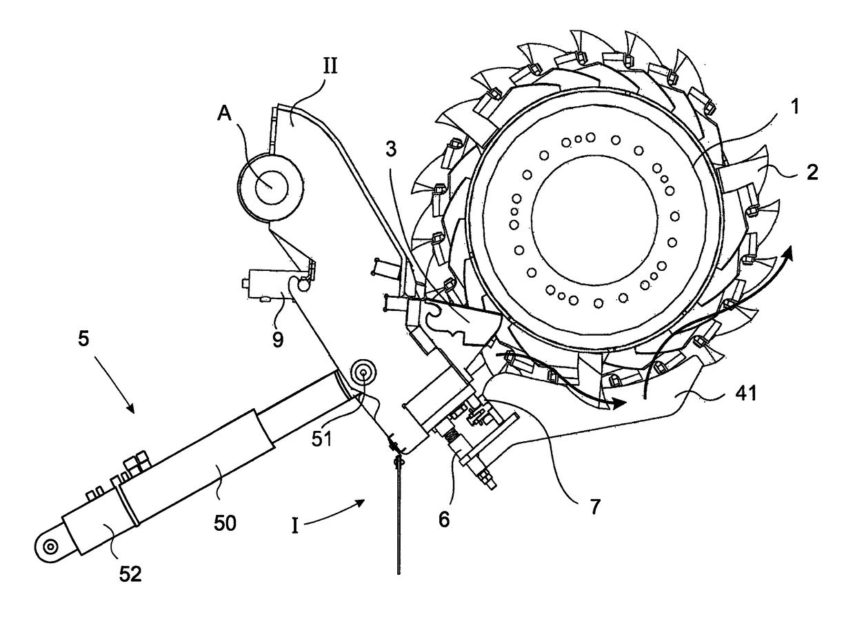
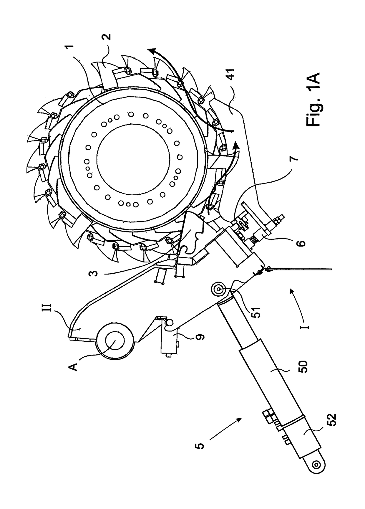
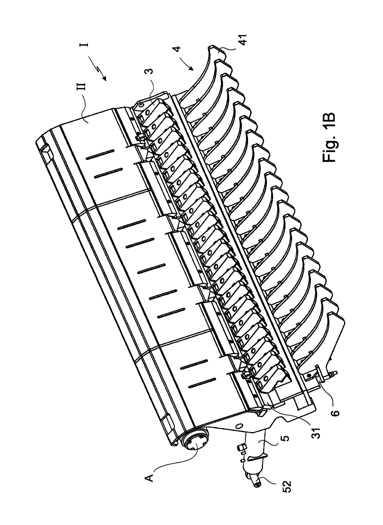
[0035]FIGS. 1A to 3C show side views and three-dimensional presentations of the base comb II provided with sieve elements 41 of the disintegrating device according to the invention. In FIGS. 1A and 1C the disintegrating roller 1 is shown with disintegrating tools 2 arranged thereon. The disintegrating roller 1 is arranged in a not shown frame as well as the base comb II with the elements arranged thereon that will be described later on. An arrow and reference number I schematically indicate the comb system according to the invention. It consist...


PUM


Abstract

The invention relates to a disintegrating device comprising a comb system (I), wherein the disintegrating device is formed by at least one disintegrating roller (1), rotatably mounted in a machine frame, with at least one disintegrating tool (2) arranged thereon, wherein the disintegrating device has at least one counter blade (3) that cooperates with the disintegrating tool (2), and comprising at least one base comb (II) on which the at least one counter blade (3) is arranged, and on which at least one sieve element (41) can be arranged as a component of a sieve device (4), wherein the sieve device (4) at least partially comprises the disintegrating roller (1) in the intended application. The invention is characterised in that the sieve element (41) is spring-mounted on the base comb (II).

Description

BACKGROUND OF THE INVENTION[0001]The invention relates to a disintegrating device comprising a comb system, wherein the disintegrating device is formed by at least one disintegrating roller, rotatably mounted in a machine frame, with at least one disintegrating tool arranged thereon, wherein the disintegrating device has at least one counter blade that cooperates with the disintegrating tool, and comprising at least one base comb on which the at least one counter blade is arranged, and on which at least one sieve element can be arranged as a component of the sieve device, wherein the sieve device at least partially encircles the disintegrating roller in the intended application.DESCRIPTION OF RELATED ART[0002]Disintegrating devices of this kind are sufficiently known in the state of the art. The known disintegrating devices, however, have the disadvantage that the sieve elements, when used as intended, during disintegrating of material to be disintegrated loaded with solid material ...

Claims


Application Information

Patent Timeline
IPC IPC(8): B02C23/16B02C18/18B02C18/22
CPCB02C23/16B02C18/18B02C2023/165B02C2018/188B02C18/2216B02C13/284B02C18/145
Inventor DOPPSTADT, JOHANNBERGER, HORST
Owner DOPPSTADT FAMILIENHOLDING GMBH
Why Eureka
Try Eureka