Method for estimating thermal sensation, thermal sensation estimation apparatus, air conditioner, and recording medium

a technology of thermal sensation and estimation apparatus, which is applied in the direction of optical radiation measurement, instruments, and sensing radiation from moving bodies, can solve the problems of inpracticality and the need of temperature sensor, and achieve the effect of accurate estimation

Active Publication Date: 2017-12-28
PANASONIC CORP
View PDF2 Cites 8 Cited by
  • Summary
  • Abstract
  • Description
  • Claims
  • Application Information

AI Technical Summary

Benefits of technology

[0006]With the method for estimating thermal sensation according to the aspect of the present disclosure, thermal sensation can be accurately estimated in accordance with a thermal environment.

Problems solved by technology

When this kind of thermal sensation estimation apparatus is used, however, a temperature sensor needs to be directly attached to a person's skin, which is not practical.

Method used


Image

  • Method for estimating thermal sensation, thermal sensation estimation apparatus, air conditioner, and recording medium
  • Method for estimating thermal sensation, thermal sensation estimation apparatus, air conditioner, and recording medium
  • Method for estimating thermal sensation, thermal sensation estimation apparatus, air conditioner, and recording medium

Examples


first embodiment

1-1. Configuration of Thermal Sensation Estimation Apparatus

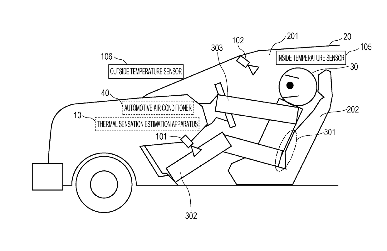
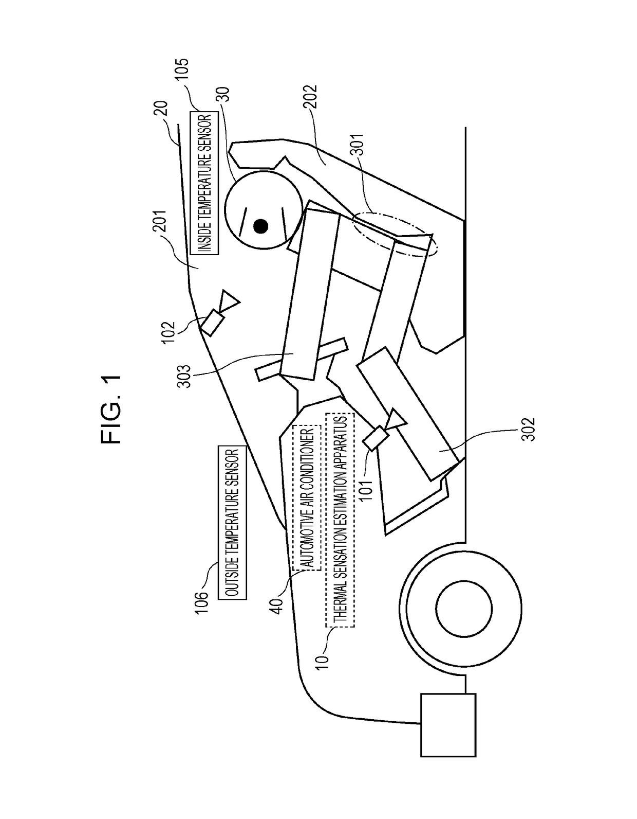
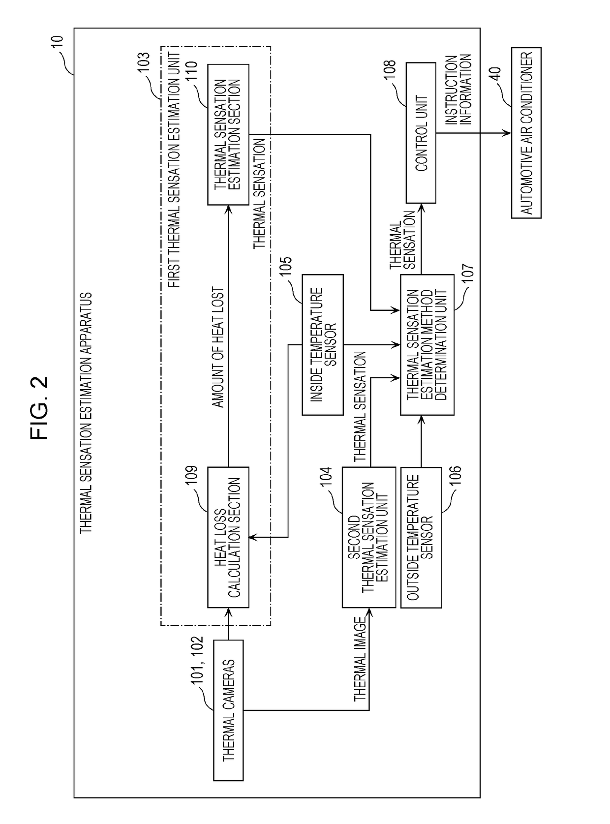
[0059]First, the configuration of a thermal sensation estimation apparatus 10 according to a first embodiment will be described with reference to FIGS. 1 and 2. FIG. 1 is a diagram illustrating a use case of the thermal sensation estimation apparatus 10 according to the first embodiment. FIG. 2 is a block diagram illustrating the configuration of the thermal sensation estimation apparatus 10 according to the first embodiment.

[0060]As illustrated in FIG. 1, for example, the thermal sensation estimation apparatus 10 is installed in an inside of a vehicle body 201 (an example of an inside of a room) of an automobile 20 (an example of a vehicle). When, in winter (or summer), a person 30 gets in the vehicle body 201 in which a heating operation (or a cooling operation) is being performed, for example, the thermal sensation estimation apparatus 10 estimates thermal sensation of the person 30 (a driver or the like) in a seat 202 o...

second embodiment

2-1. Configuration of Thermal Sensation Estimation Apparatus

[0096]Next, the configuration of a thermal sensation estimation apparatus 10A according to a second embodiment will be described with reference to FIGS. 4 and 5. FIG. 4 is a diagram illustrating a use case of the thermal sensation estimation apparatus 10A according to the second embodiment. FIG. 5 is a block diagram illustrating the configuration of the thermal sensation estimation apparatus 10A according to the second embodiment. In the present embodiment, the same components as those according to the first embodiment are given the same reference numerals, and description thereof is omitted.

[0097]In the present embodiment, a case will be described in which the automotive air conditioner 40 performs a heating operation in winter. As illustrated in FIG. 4, seat heaters 203 for heating a back of the person 30 are installed in the seat 202 of the automobile 20.

[0098]As illustrated in FIGS. 4 and 5, the thermal sensation estima...


PUM

PropertyMeasurementUnit
temperatureaaaaaaaaaa
thermal sensation estimation apparatusaaaaaaaaaa

Abstract

In a method for estimating thermal sensation, thermal environment information at least regarding a thermal environment of or around a person is obtained, (1) a method for estimating a first thermal sensation, (2) a method for estimating a second thermal sensation, or (3) both the method for estimating the first thermal sensation and the method for estimating the second thermal sensation is selected as a method for estimating thermal sensation, which indicates a degree of warmth or coldness of the person, on the basis of the thermal environment information, and the thermal sensation is estimated using the selected method.

Description

BACKGROUND1. Technical Field[0001]The present disclosure relates to a method for estimating thermal sensation, a thermal sensation estimation apparatus, an air conditioner, and a recording medium.2. Description of the Related Art[0002]A thermal sensation estimation apparatus that estimates thermal sensation, which indicates a degree of warmth or coldness of a person, without a report from the person is known. When the thermal sensation estimation apparatus is installed in an automobile, for example, an automotive air conditioner can be efficiently operated by controlling the air temperature of the automotive air conditioner or the like on the basis of the estimated thermal sensation.[0003]One of thermal sensation estimation apparatuses in examples of the related art is one that estimates thermal sensation by measuring an average skin temperature of a person on the basis of a fact that the average skin temperature and the thermal sensation have a high correlation. When this kind of t...

Claims


Application Information

Patent Timeline
Patent Type & Authority Applications(United States)
IPC IPC(8): B60H1/00G01J5/00G06V10/143
CPCB60H1/00742G06K9/2018G01J2005/0077G01J5/0025G01J5/026G06V20/597G06V10/143
Inventor YONEDA, AKIKUSUKAME, KOICHIKUBO, HIROKO
Owner PANASONIC CORP
Why Eureka
Try Eureka