
3D spiral heat exchanger

a heat exchanger and spiral technology, applied in indirect heat exchangers, lighting and heating apparatuses, laminated elements, etc., can solve the problems of heat exchanger type, solids or fouling, and higher cos

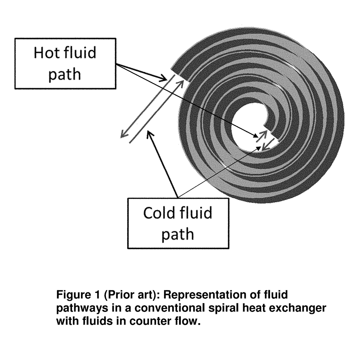
Active Publication Date: 2017-12-28
FLUID HANDLING
View PDF5 Cites 10 Cited by
  • Summary
  • Abstract
  • Description
  • Claims
  • Application Information

AI Technical Summary

Benefits of technology

The invention described in this patent is adaptable to various situations and materials without needing to be limited to the specific embodiment disclosed. This allows for flexibility and customization in application of the invention without being limited to the specifics.

Problems solved by technology

This means that, not only will the fluid flow more efficiently, but there is also no particular region that would encourage the deposition of solids or fouling, in fact the design in self-cleaning.
There are also disadvantages to this type of heat exchanger.
First, its relatively complex geometry usually results in a higher cost.
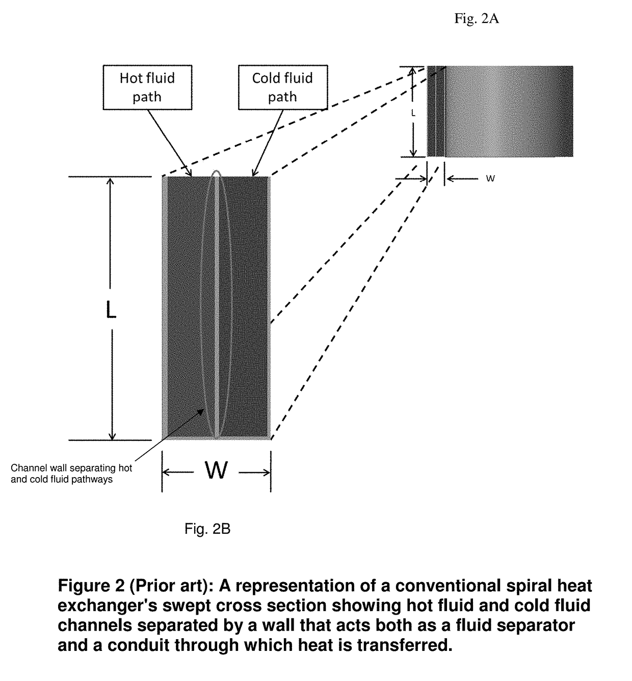
Second, the large single channels limit the area available for heat transfer and the pressure range for the device.

Method used


Image

  • 3D spiral heat exchanger
  • 3D spiral heat exchanger
  • 3D spiral heat exchanger

Examples


example of an embodiment

[0029]According to some embodiments, the present invention may take the form of a new and unique 3D spiral heat exchanger generally indicated as 10.

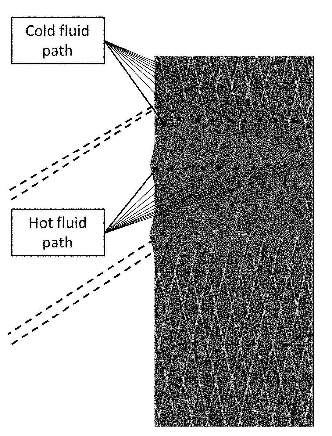
[0030]The 3D spiral heat exchanger 10 includes first spiral channels configured to form rows and columns of coiled hot fluid pathways to receive hot fluid. For hot fluid flowing from the outer / peripheral portion to the inner / central portion of the 3D spiral heat exchange 10, the hot fluid paths or channels are shown and designated in FIG. 4B as rows and columns, as follows:

[0031]r2, c1; r4, c1; r6, c1; r8, c1; r10, c1;

[0032]r2, c3; r4, c3; r6, c3; r8, c3; r10, c3;

[0033]r2, c5; r4, c5; r6, c5; r8, c5; r10, c5;

[0034]. . . ;

[0035]r2, c17; r4, c17; r6, c17; r8, c17; r10, c17; and

[0036]r2, c19; r4, c19; r6, c19; r8, c19; r10, c19.

[0037]The 3D spiral heat exchanger 10 includes second spiral channels configured to form corresponding rows and columns of coiled cold fluid pathways to receive cold fluid having a temperature less than the hot fluid...


PUM

PropertyMeasurementUnit
temperatureaaaaaaaaaa
heat transfer capabilityaaaaaaaaaa
pressureaaaaaaaaaa

Abstract

A spiral heat exchanger features first spiral channels configured to form rows and columns of coiled hot fluid pathways to receive hot fluid; and second spiral channels configured to form corresponding rows and columns of coiled cold fluid pathways to receive cold fluid having a temperature less than the hot fluid. The first spiral channels and the second spiral channels are configured to alternate every other row and column so as to form a matrix of alternating rows and columns of coiled hot and cold fluid pathways separated by alternating coiled walls that act as both fluid separators and conduits through which heat is transferred between the hot fluid and cold fluid.

Description

CROSS-REFERENCE TO RELATED APPLICATIONS[0001]This application claims benefit to provisional patent application Ser. No. 62 / 347,813 (911-026.001-1 (F-STD-X0001 US01)), filed 9 Jun. 2016; which is incorporated by reference in its entirety.BACKGROUND OF THE INVENTION1. Field of Invention[0002]This invention relates to a heat exchanger; and more particularly, to a heat exchanger to lower or raise the temperature of a fluid by facilitating heat transfer between that fluid with another fluid at a different temperature.2. Description of Related Art[0003]A heat exchanger is a device whose purpose is to lower or raise the temperature of a fluid by facilitating heat transfer between that fluid with another fluid at a different temperature. There are several types of heat exchangers available that vary in heat transfer capability; geometrical design and complexity; cost; working fluid temperature, pressure, and viscosity ranges; and many other attributes.[0004]Common types of heat exchangers i...

Claims


Application Information

Patent Timeline
Patent Type & Authority Applications(United States)
IPC IPC(8): F28D9/04F28F3/04F28F3/12
CPCF28D9/04F28F3/12F28F3/04F28F1/04B33Y80/00F28D7/02F28D7/04F28D7/0016F28F7/02F28F2255/18B22F5/10B22F10/28Y02P10/25
Inventor LOPES, JEFFREY D.
Owner FLUID HANDLING
Learn More