Machining program editing apparatus, method, and storage medium

a technology of program editing and program, applied in the direction of program control, total factory control, instruments, etc., can solve the problem of not being able to reduce the man-hour as effectively, and achieve the effect of reducing the time required for searching and facilitating the validation of the content of the code statemen

Active Publication Date: 2017-12-28
FANUC LTD
View PDF7 Cites 6 Cited by
  • Summary
  • Abstract
  • Description
  • Claims
  • Application Information

AI Technical Summary

Benefits of technology

[0011]In the first aspect of the invention, the apparatus may further include a data acquisition unit configured to analyze the machining program and acquire search data in which feature points of the sections are associated with the block numbers, and a block information searching unit configured to search the search data acquired by the data acquisition unit for one of the block numbers in which one of the feature points of the sections coincides with the start point or the end point. Since, after the search data containing the data needed for editing is acquired from the machining program having a large amount of data, a searching process is performed based on the search data, this makes it possible to markedly reduce the time required for searching for feature points in the sections and block numbers.
[0012]In the first aspect of the invention, the program editing unit may edit the machining program by assigning a specific character for partially invalidating readout of data, to the code statement. This configuration makes it possible to easily validate the content of a code statement by deleting the specific character afterwards.
[0013]Further, in the first aspect of the invention, the program editing unit may edit the machining program by deleting the code statement to which the specific character is assigned, together with the specific character, in accordance with a confirming operation performed by the operator using the GUI unit. This feature makes it possible to prevent automatic confirmation of the edited content of the machining program against operator's intention.
[0014]In the first aspect of the invention, the GUI unit may lay the indication route on the original machining path in the display area and display the indication route in a display form different from that of the area from the start point to the end point on the original machining path. This enables the operator to grasp the difference between the machining paths before and after modification at a glance.

Problems solved by technology

As a result, this device entails the problem that it is not as effective in reducing the man-hour as expected.

Method used


Image

  • Machining program editing apparatus, method, and storage medium
  • Machining program editing apparatus, method, and storage medium
  • Machining program editing apparatus, method, and storage medium

Examples


Embodiment Construction

[0040]A preferred embodiment of a machining program editing apparatus according to the present invention will be described below in detail with reference to the accompanying drawings in relation to a machining program editing method and an editing program.

[Configuration Diagram of Numerical Controller 10]

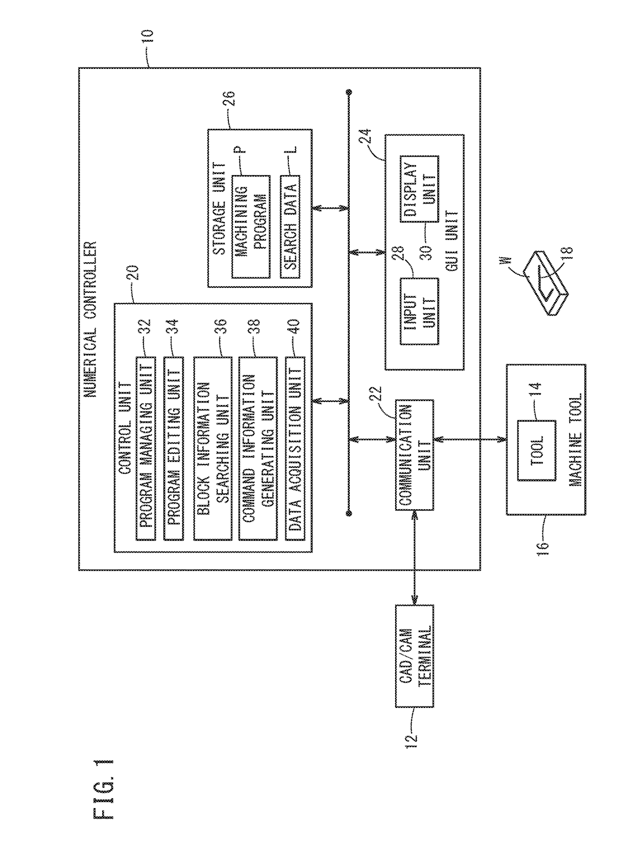
[0041]FIG. 1 is a configuration diagram of a numerical controller 10 as a machining program editing apparatus in this embodiment. The numerical controller 10 is a higher-level host device that uses a machining program P created by a CAD (Computer Aided Design) / CAM (Computer Aided Manufacturing) terminal 12 to comprehensively control a machine tool 16 (one or more lower-level devices) having a tool 14.

[0042]Hereinbelow, in order to clearly distinguish differences in content, machining programs P before editing, during editing, and after editing may be referred to as P1, P2, and P3, respectively.

[0043]In accordance with the machining program P, the machine tool 16 performs a machining...


PUM


Abstract

A machining program editing apparatus includes a GUI unit configured to specify an indication route having two points located on an original machining path, as a start point and an end point, and a program editing unit configured to edit a machining program indicative of the original machining path to thereby form a new machining path by replacing an area from the start point to the end point on the original machining path, with the indication route specified through the GUI unit.

Description

CROSS-REFERENCE TO RELATED APPLICATION[0001]This application is based upon and claims the benefit of priority from Japanese Patent Application No. 2016-125541 filed on Jun. 24, 2016, the contents of which are incorporated herein by reference.BACKGROUND OF THE INVENTIONField of the Invention:[0002]The present invention relates to a machining program editing apparatus, a method, and a storage medium that edit a machining program for causing a machine tool to machine a workpiece along a machining path composed of two or more sections.Description of the Related Art:[0003]Conventionally, a variety of machining program editors that enable edition of machining programs for controlling machine tools have been developed.[0004]International Publication No. WO 2016 / 035868 discloses an editing assistance device that displays a machining path and a code statement at the same time and moves a cursor to a position corresponding to a point designated by the displayed code statement, by designating ...

Claims


Application Information

Patent Timeline
Patent Type & Authority Applications(United States)
IPC IPC(8): G05B19/4097
CPCG05B19/4097G05B2219/32128G05B2219/35012G05B2219/36266Y02P90/02
Inventor KIMURA, SATOSHIKANEMARU, AKIRA
Owner FANUC LTD
Why Eureka
Try Eureka