
Motor driving apparatus and method of controlling the same

a technology of motor driving and motor gear, which is applied in the direction of dynamo-electric converter control, dynamo-electric brake control, dynamo-electric gear control, etc., to achieve the effect of reducing losses in motors

Active Publication Date: 2017-12-28
SAMSUNG ELECTRONICS CO LTD
View PDF5 Cites 25 Cited by
  • Summary
  • Abstract
  • Description
  • Claims
  • Application Information

AI Technical Summary

Benefits of technology

The motor driving apparatus and method of controlling it can reduce motor losses by adjusting the driving current and DC voltage to compensate for copper and iron losses, as well as inverter and power supply losses. This results in a more efficient motor and improved performance.

Problems solved by technology

In a motor, a copper loss that is a current loss consumed during conversion of electric energy into mechanical energy, an iron loss that is a magnetic flux loss consumed during rotation of the motor, and a loss by a power conversion unit such as a power supply and an inverter occur.

Method used


Image

  • Motor driving apparatus and method of controlling the same
  • Motor driving apparatus and method of controlling the same
  • Motor driving apparatus and method of controlling the same

Examples


Embodiment Construction

Technical Problem

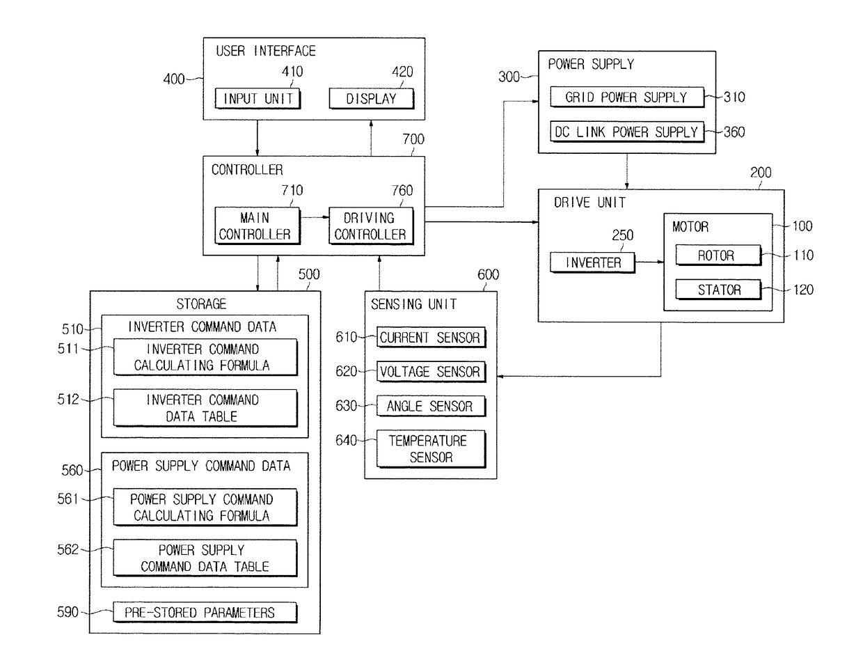
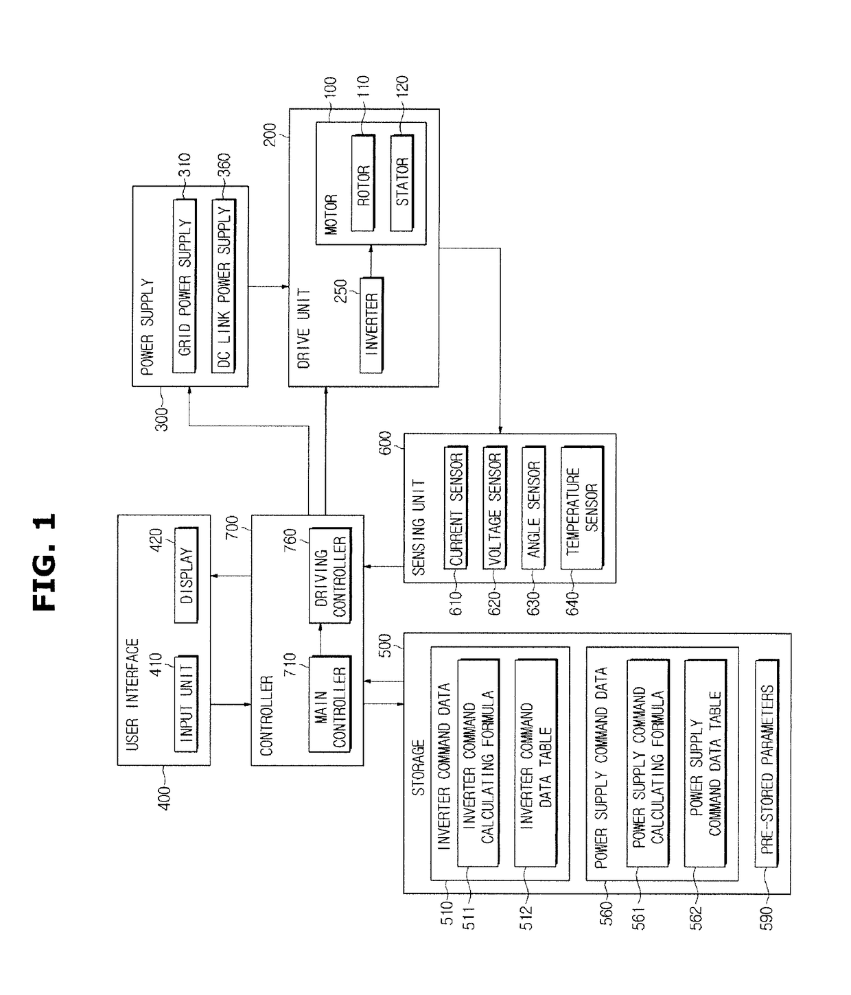
[0004]An aspect of the present disclosure is to provide a motor driving apparatus configured to adjust a driving current to compensate for a copper loss and an iron loss and adjust a direct current (DC) voltage to compensate for losses of an inverter and a power supply, and a method of controlling the same.

Technical Solution

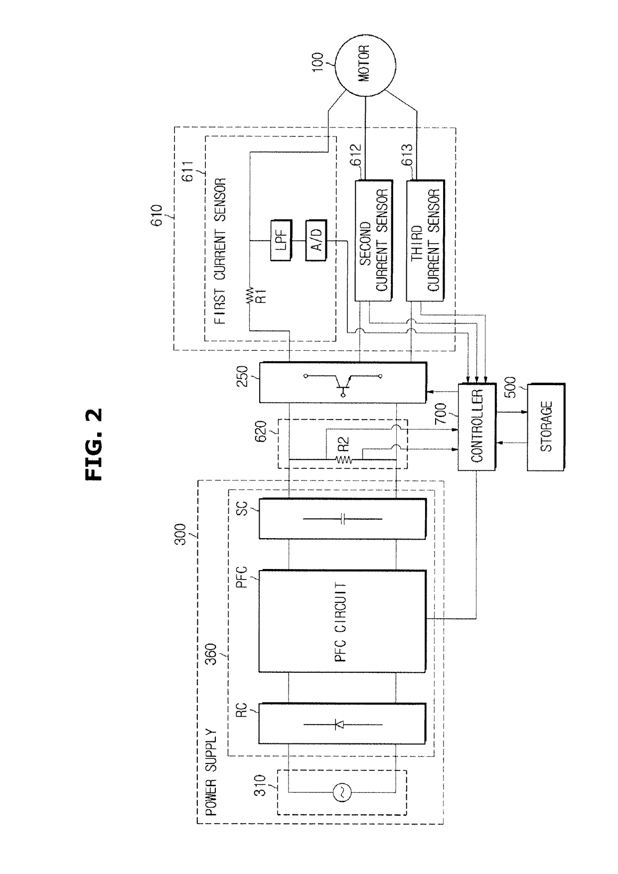
[0005]In accordance with one aspect of the present disclosure, a motor driving apparatus includes an inverter configured to supply driving power to a motor; a sensing unit configured to sense a DC voltage supplied to the inverter and a driving current supplied from the inverter to the motor; and a controller configured to compensate for an iron loss and a copper loss by calculating a loss of the motor based on the sensed DC voltage and driving current and controlling the inverter to adjust the driving current based on the calculated loss of the motor.

[0006]The controller may compensate for the iron loss and the copper loss by calculating a temper...


PUM


Abstract

It is an aspect of the present disclosure to provide a motor driving apparatus, and a method of controlling the same. In accordance with one aspect of the present disclosure, the motor driving apparatus includes an inverter configured to supply driving power to a motor; a sensing unit configured to sense a DC voltage supplied to the inverter and a driving current supplied from the inverter to the motor; and a controller configured to compensate for an iron loss and a copper loss by calculating a loss of the motor based on the sensed DC voltage and driving current and controlling the inverter to adjust the driving current based on the calculated loss of the motor.

Description

TECHNICAL FIELD[0001]The present disclosure relates to a motor driving apparatus to compensate for losses occurring while a motor is driven and a method of controlling the same.BACKGROUND ART[0002]A motor is a machine designed to obtain a rotational force from electric energy and may include a stator and a rotor. The rotor is configured to electromagnetically interact with the stator and may rotate by a force acting between a magnetic field and a current flowing in coils.[0003]In a motor, a copper loss that is a current loss consumed during conversion of electric energy into mechanical energy, an iron loss that is a magnetic flux loss consumed during rotation of the motor, and a loss by a power conversion unit such as a power supply and an inverter occur. Although maximum torque per ampere (MTPA) control methods have been widely used conventionally, only the copper loss is compensated for thereby. Thus, recently, extensive research has been conducted into methods of compensating for...

Claims


Application Information

Patent Timeline
Patent Type & Authority Applications(United States)
IPC IPC(8): H02P27/08H02P21/22H02P29/60
CPCH02P27/08H02P21/22H02P29/67H02P27/06H02P21/0025H02P21/16H02P21/20H02P29/60
Inventor SHIN, JONG HYUNKIM, SUN JINKIM, JIN HAN
Owner SAMSUNG ELECTRONICS CO LTD
Learn More