
Systems, methods, and devices for geolocation with deployable large scale arrays

Active Publication Date: 2017-12-28
DIGITAL GLOBAL SYST INC
View PDF5 Cites 73 Cited by
  • Summary
  • Abstract
  • Description
  • Claims
  • Application Information

AI Technical Summary

Benefits of technology

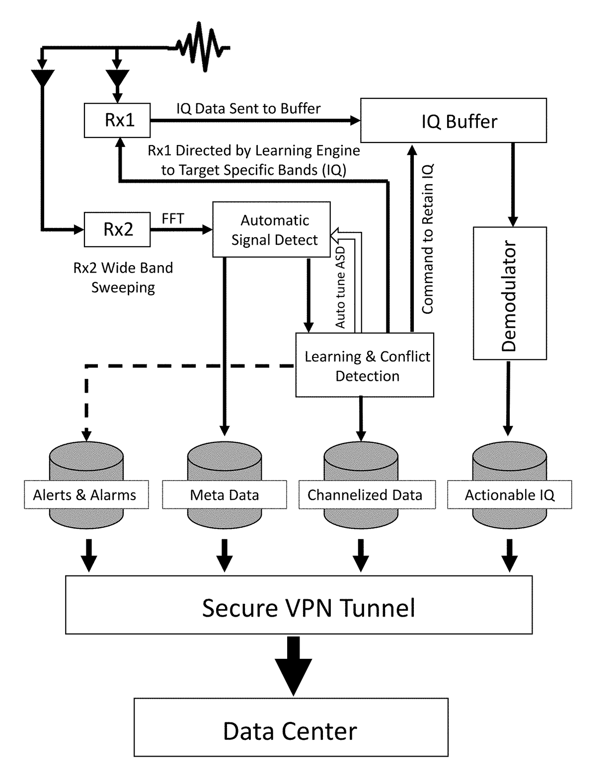
The present invention provides systems, apparatus, and methods for identifying open space in a wireless communications spectrum using an apparatus with multiple processors and memory, sensors, and communication transmitters and receivers. This enables near real-time analysis of detected signals from signal emitting devices and automatic generation of information related to device identification, signal optimization, and open space identification. The information can be stored securely and accessed remotely via a network. Overall, the invention facilitates unique comparisons of data within the spectrum for wireless communication and enhances efficiency in wireless communication network

Problems solved by technology

A problem faced in effective spectrum management is the various numbers of devices emanating wireless signal propagations at different frequencies and across different technological standards.
Coupled with the different regulations relating to spectrum usage around the globe effective spectrum management becomes difficult to obtain and at best can only be reached over a long period of time.
Another problem facing effective spectrum management is the growing need from spectrum despite the finite amount of spectrum available.
Problems arise with these narrowly tailored devices as cellular standards change and / or spectrum use changes impact the spectrum space of these technologies.
Changes to the software and hardware for these narrowly tailored devices become too complicated, thus necessitating the need to purchase a totally different and new device.
Unfortunately, this type of device is only for a specific use and cannot be used to alleviate the entire needs of the spectrum management community.
The second type of spectral management device employs a methodology that requires bulky, extremely difficult to use processes, and expensive equipment.
In order to attain a broad spectrum management view and complete all the necessary tasks, the device ends up becoming a conglomerate of software and hardware devices that is both hard to use and difficult to maneuver from one location to another.
While there may be several additional problems associated with current spectrum management devices, at least four major problems exist overall: 1) most devices are built to inherently only handle specific spectrum technologies such as 900 MHz cellular spectrum while not being able to mitigate other technologies that may be interfering or competing with that spectrum, 2) the other spectrum management devices consist of large spectrum analyzers, database systems, and spectrum management software that is expensive, too bulky, and too difficult to manage for a user's basic needs, 3) other spectrum management devices in the prior art require external connectivity to remote databases to perform analysis and provide results or reports with analytics to aid in management of spectrum and / or devices, and 4) other devices of the prior art do not function to provide real-time or near real-time data and analysis to allow for efficient management of the space and / or devices and signals therein.
However, none of the prior art references provide solutions to the limitations and longstanding unmet needs existing in this area for automatically identifying open space in a wireless communications spectrum.

Method used


Image

  • Systems, methods, and devices for geolocation with deployable large scale arrays
  • Systems, methods, and devices for geolocation with deployable large scale arrays
  • Systems, methods, and devices for geolocation with deployable large scale arrays

Examples


Embodiment Construction

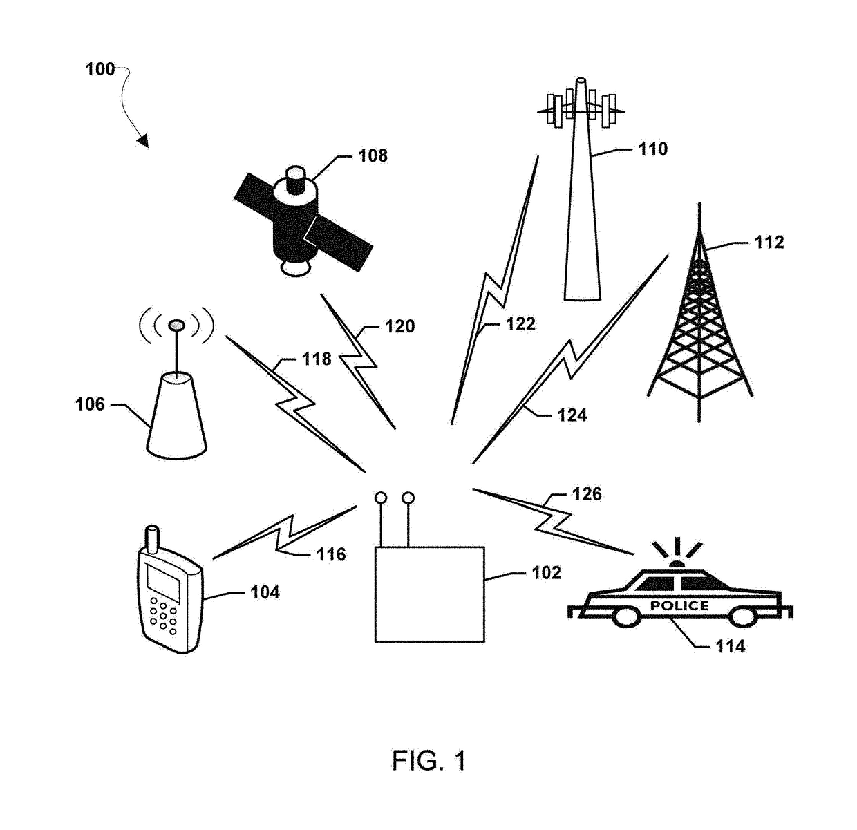
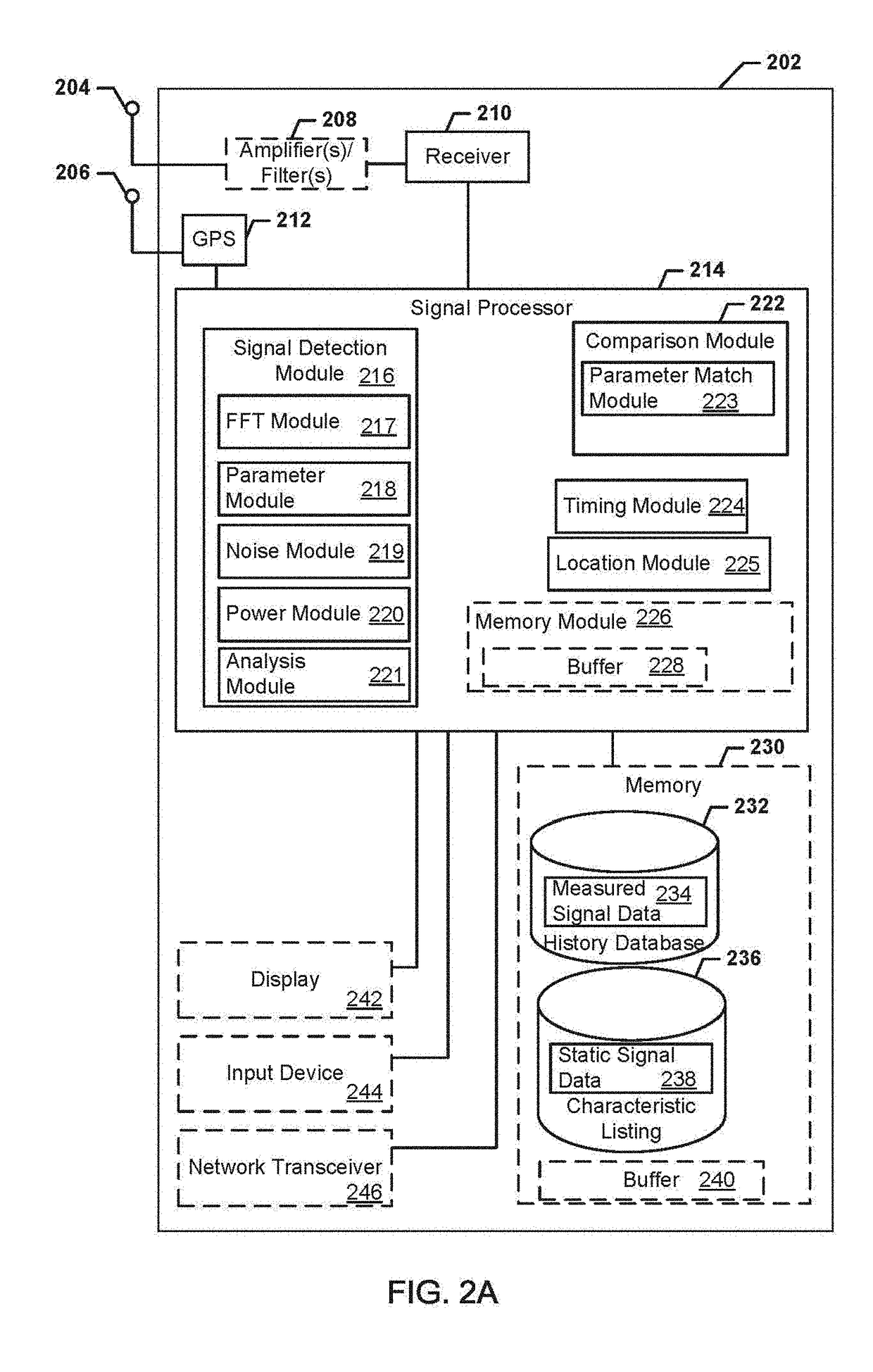
[0097]Referring now to the drawings in general, the illustrations are for the purpose of describing at least one preferred embodiment and / or examples of the invention and are not intended to limit the invention thereto. Various embodiments are described in detail with reference to the accompanying drawings. Wherever possible, the same reference numbers are used throughout the drawings to refer to the same or like parts. References made to particular examples and implementations are for illustrative purposes, and are not intended to limit the scope of the invention or the claims.

[0098]The word “exemplary” is used herein to mean “serving as an example, instance, or illustration.” Any implementation described herein as “exemplary” is not necessarily to be construed as preferred or advantageous over other implementations.

[0099]The present invention provides systems, methods, and devices for spectrum analysis and management by identifying, classifying, and cataloging at least one or a mu...


PUM


Abstract

Systems, methods, and apparatus for geolocating a signal emitting device are disclosed. A monitoring array comprises at least four monitoring units. A distance ratio between the at least four monitoring units relative to a midpoint is determined. The at least four monitoring units are operable to scan independently for a signal of interest. The at least four monitoring units are operable to calculate times of arrival and angles of arrival for the signal of interest. Each of the at least four monitoring units is operable to measure the signal of interest and transmit a formatted message to other monitoring units within the monitoring array. Each of the at least four monitoring units is operable to determine a location of the signal emitting device from which the signal of interest is emitted based on calculations and measurements relating to the signal of interest.

Description

CROSS-REFERENCE TO RELATED APPLICATIONS[0001]This application relates to and claims priority from the following applications. This application is a continuation-in-part of U.S. application Ser. No. 15 / 478,916 filed Apr. 4, 2017 and a continuation-in-part of U.S. application Ser. No. 15 / 412,982 filed Jan. 23, 2017. U.S. application Ser. No. 15 / 478,916 is continuation-in-part of U.S. application Ser. No. 14 / 934,808 filed Nov. 6, 2015, which is a continuation of U.S. application Ser. No. 14 / 504,836 filed Oct. 2, 2014, which is a continuation of U.S. application Ser. No. 14 / 331,706 filed Jul. 15, 2014, which is a continuation-in-part of U.S. application Ser. No. 14 / 086,875 filed Nov. 21, 2013. U.S. application Ser. No. 14 / 086,875 is a continuation-in-part of U.S. application Ser. No. 14 / 082,873 filed Nov. 18, 2013, which is a continuation of U.S. application Ser. No. 13 / 912,683 filed Jun. 7, 2013, which claims the benefit of U.S. Provisional Application 61 / 789,758 filed Mar. 15, 2013, e...

Claims


Application Information

Patent Timeline
IPC IPC(8): H04W24/08H04B17/27H04B17/23H04B17/26H04B17/309H04B17/29
CPCH04B17/29H04B17/26H04B17/23H04B17/309H04B17/27H04W24/08H04W24/04H04W24/10H04B17/20H04B17/24H04W64/00
Inventor KLEINBECK, DAVID WILLIAMDZIERWA, RONALD C.CARBAJAL, DANIEL
Owner DIGITAL GLOBAL SYST INC
Learn More