Positioning in beamformed communications

a beam-formed communication and positioning technology, applied in the field of positioning in mmw communications, can solve problems such as the challenge of determining the location of ues operating in wireless networks

Active Publication Date: 2017-12-28
QUALCOMM INC
View PDF3 Cites 91 Cited by
  • Summary
  • Abstract
  • Description
  • Claims
  • Application Information

AI Technical Summary

Benefits of technology

[0007]The described techniques relate to improved methods, systems, devices, or apparat

Problems solved by technology

Determining the location of UEs operating in wireless networks may be a challenge owing t

Method used


Image

  • Positioning in beamformed communications
  • Positioning in beamformed communications
  • Positioning in beamformed communications

Examples


Embodiment Construction

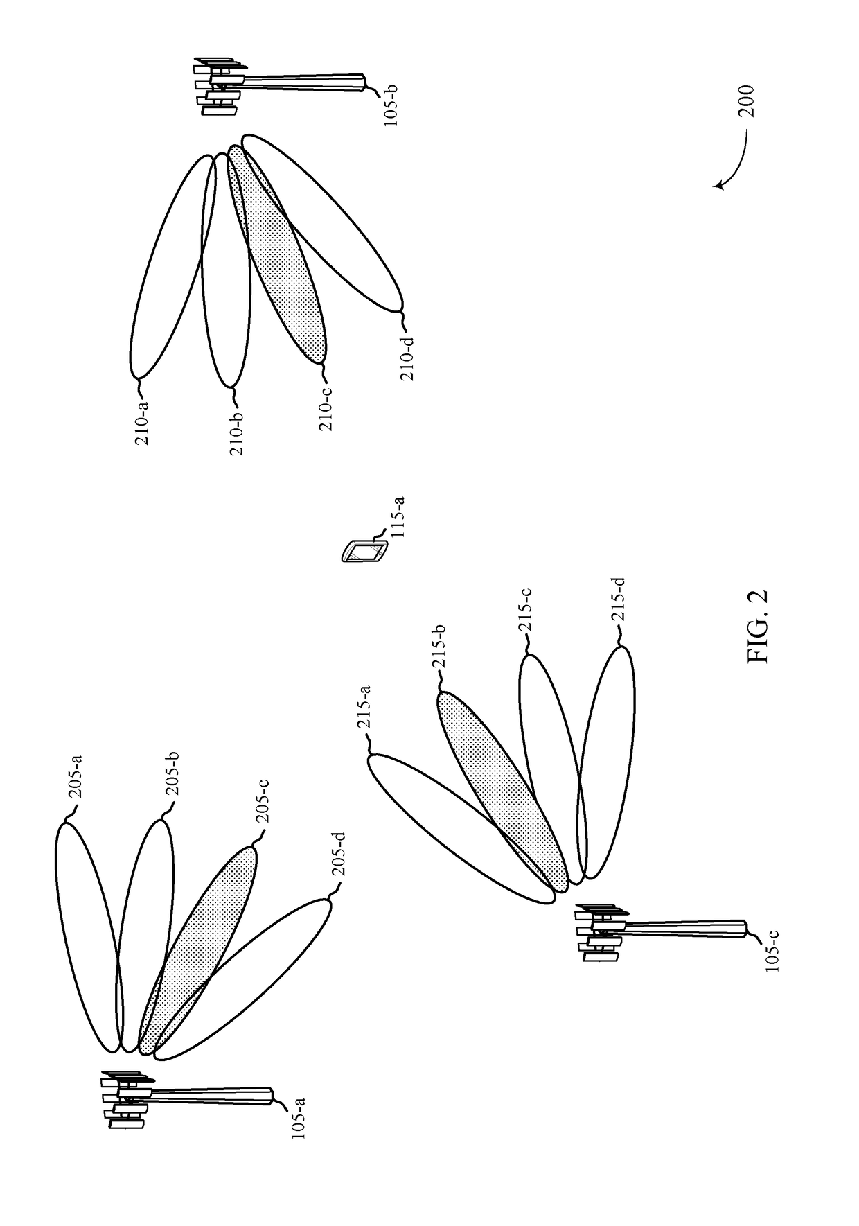
[0047]Some wireless communication systems (e.g., LTE) may use two types of positioning mechanisms—downlink-based (e.g., observed time difference of arrival (OTDOA)) and uplink-based (e.g., uplink time difference of arrival (UT-DOA)). In the downlink-based positioning, a PRS is transmitted with a certain periodicity on the downlink. The UE measures the difference between the arrival times of the PRS from multiple eNodeBs, and reports this back to the network. The network uses these reports and the known base station locations in order to determine the UE location. The PRS may be broadcast from each base station with strong enough power to be heard not only by the UEs in that cell, but also by those in neighboring cells. Accurate positioning may use reports from multiple base stations.

[0048]Uplink-based positioning may be transparent to the UE, and may include the network measuring a time-delay of arrival of the UE uplink at various base stations. This may be feasible because the UE t...


PUM


Abstract

Methods, systems, and devices for wireless communication are described. A base station may receive a first measurement report from a user equipment (UE) that includes an indication of a measurement parameter associated with a first beamformed reference signal. The base station may receive additional measurement reports from the UE for additional base stations. The additional measurement reports may include an indication of measurement parameters associated with additional beamformed reference signals transmitted by the additional base stations. The base station may identify a location of the UE based on the first measurement report and the additional measurement report. Alternatively, the UE may transmit multiple beamformed sounding reference signals to multiple base stations, and a single base station may identify a location of the UE based on multiple reports collected from the multiple base stations.

Description

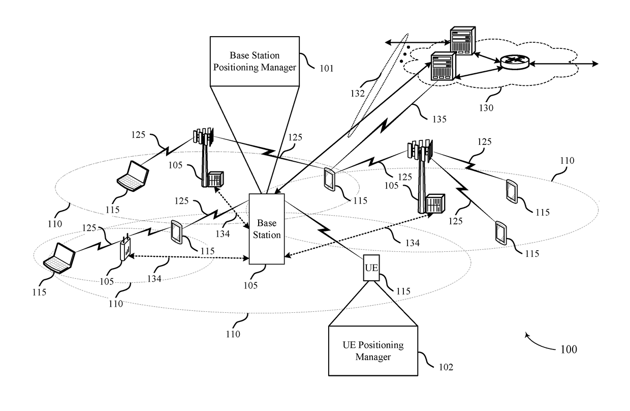
CROSS REFERENCES[0001]The present application for patent claims priority to U.S. Provisional Patent Application No. 62 / 354,028 by Akkarakaran, et al., entitled “Positioning In Millimeter-Wave Communications,” filed Jun. 23, 2016, assigned to the assignee hereof.INTRODUCTION[0002]The following relates generally to location determination in beamformed communication, such as millimeter-wave (mmW) wireless communication, and more specifically to positioning in mmW communications.[0003]Wireless communications systems are widely deployed to provide various types of communication content such as voice, video, packet data, messaging, broadcast, and so on. These systems may be capable of supporting communication with multiple users by sharing the available system resources (e.g., time, frequency, and power). Examples of such multiple-access systems include code division multiple access (CDMA) systems, time division multiple access (TDMA) systems, frequency division multiple access (FDMA) sys...

Claims


Application Information

Patent Timeline
IPC IPC(8): H04W64/00H04B7/06H04L5/00H04W24/10
CPCH04W64/00H04L5/0051H04W24/10H04B7/0617H04W64/006G01S5/10G01S5/12G01S5/0226H04W16/28G01S5/0036
Inventor AKKARAKARAN, SONYLUO, TAONAGARAJA, SUMEETH
Owner QUALCOMM INC
Why Eureka
Try Eureka