Multi-function gunsight

a multi-functional, gunsight technology, applied in the direction of weapons, aiming means, sighting devices, etc., can solve the problems of difficult or impossible to see dots, laser sights are not without problems, and laser sights perform poorly

Active Publication Date: 2018-01-04
BUSHNELL
View PDF0 Cites 31 Cited by
  • Summary
  • Abstract
  • Description
  • Claims
  • Application Information

AI Technical Summary

Benefits of technology

[0015]The battery compartment may be dimensioned and adapted to receive a battery. In some embodiments, the battery compartment is dimensioned and adapted to receive a battery of the size known as CR123A. The battery may comprise, for example, a CR123A lithium battery. In one or more embodiments, the battery compartment is disposed forward of the sight arm pivot axis PA. In one or more embodiments, a forward-most end of the battery compartment is disposed forward of a forward-most end of the laser cavity.
[0016]In one or more embodiments, a laser unit of the multi-function gunsight is disposed inside the laser cavity. The laser unit may generate a laser beam extending in a forward direction along a laser beam axis LA. In one or more embodiments, the laser beam axis LA is generally parallel to the gun bore axis BA of the firearm. In one or more embodiments, the laser unit is disposed forward of the sight arm pivot axis PA.
[0017]In one or more embodiments, a elevation adjustment mechanism of the multi-function gunsight is positioned opposite the battery compartment and the battery housing. The elevation adjustment mechanism may selective rotate the laser unit about a elevation axis X. In one or more embodiments, the elevation axis X extends in portward and starboard directions. In one or more embodiments, the elevation adjustment mechanism is disposed forward of the sight arm pivot axis PA. In one or more embodiments, a windage adjustment mechanism of the multi-function gunsight is positioned opposite the battery compartment and the battery housing. The windage adjustment mechanism may selective rotate the laser unit about a windage axis Y. In one or more embodiments, the windage axis Y extends in upward and downward directions. In one or more embodiments, the windage adjustment mechanism is disposed for

Problems solved by technology

Laser sights are not, however, without problems.
For example, although laser sights work well in low light conditions, in bright light conditions laser sights occasionally perform poorly because ambient light can overwhelm the dot generated on the target by the laser light source, making the dot difficult or impossible for the user to see.
A laser sight also uses a relatively large amount of power, so the battery life for a laser sight is typically relatively short.
This makes scopes difficult to aim quickly, difficult to use while tracking a moving target and difficult or impossible to us

Method used


Image

  • Multi-function gunsight
  • Multi-function gunsight
  • Multi-function gunsight

Examples


Embodiment Construction

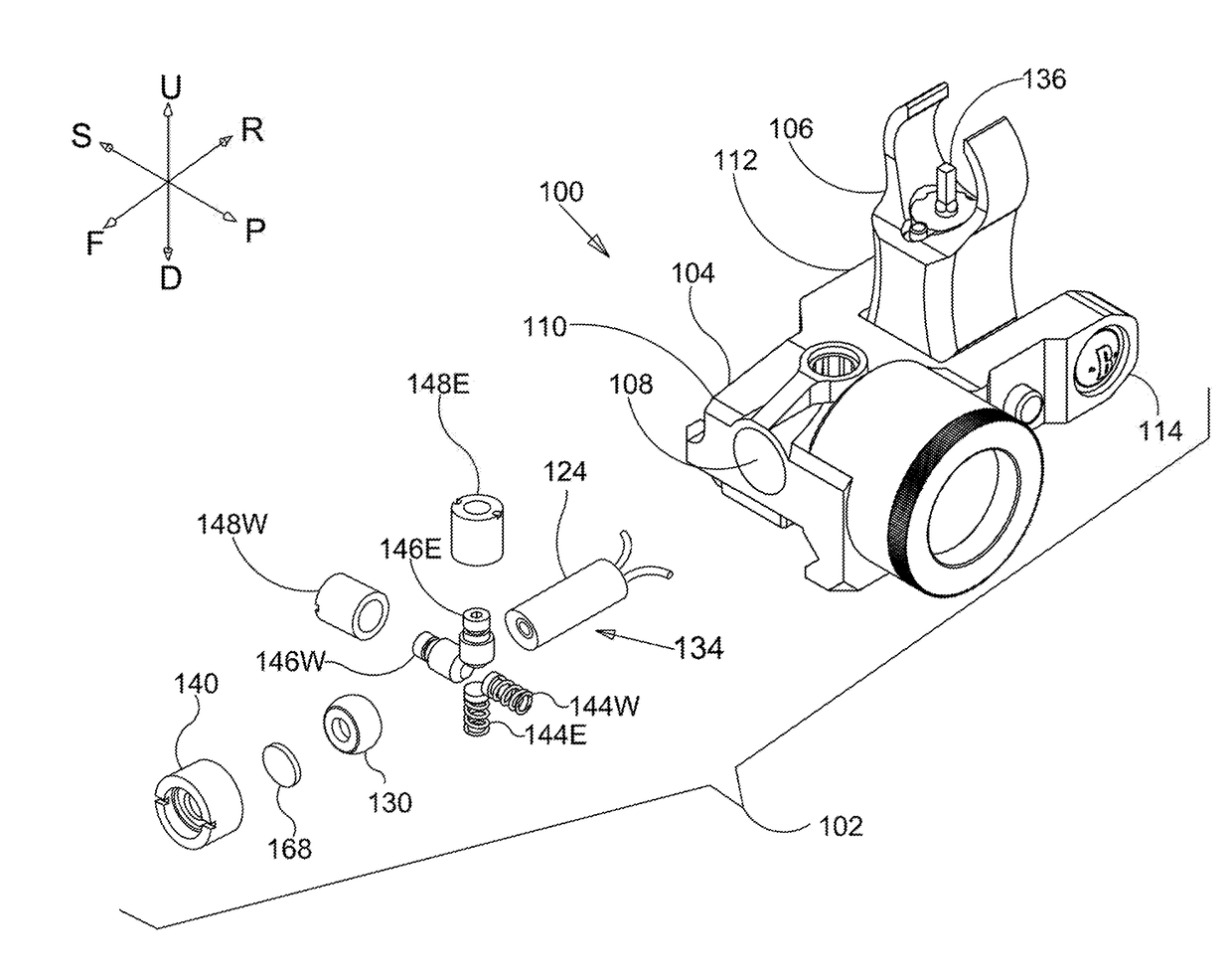
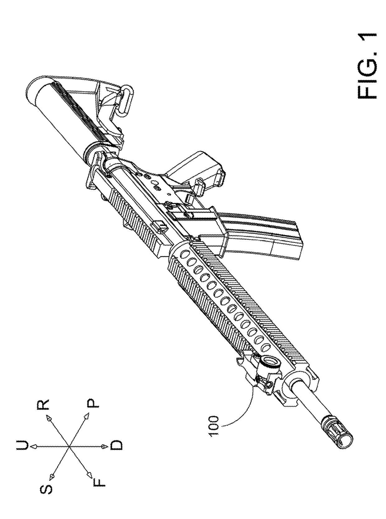
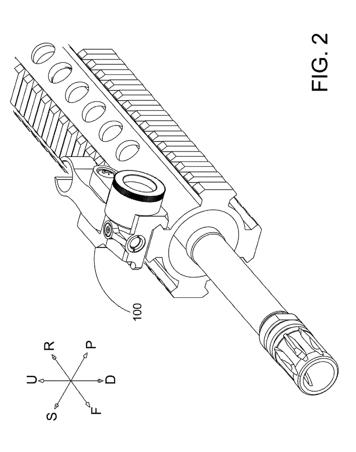
[0048]Referring to FIGS. 1-25, a multi-function gunsight 100 for aiming a firearm comprises a gunsight assembly 102 including a body 104 and a sight arm 106 pivotally coupled to the body 104 for rotation between a stowed orientation and a deployed orientation. The body 104 defines a laser cavity 108, a starboard cavity 120, and a port cavity 122. A laser unit xx is disposed inside the laser cavity 108 defined by the body 104. The laser unit xx comprises a laser housing 124. The laser housing 124 supports a semiconductor chip 126 that emits laser light and a lens 128 that collimates the laser light emitted by the semiconductor chip 126. A forward end of the laser housing 124 is coupled to a spherical bearing 130. The spherical bearing 130 constrains movement of the laser housing in three translation degrees of freedom corresponding to translation along x, y, and z axes of an x-y-z coordinate system. The spherical bearing 130 allows rotation of the laser housing 124 about at least the...


PUM


Abstract

A multi-function gunsight for aiming a firearm comprises a body and a sight arm pivotally coupled to the body for rotation between a stowed orientation and a deployed orientation. The body defining a laser cavity, a starboard cavity, and a port cavity. A laser housing is disposed inside the laser cavity defined by the body. The laser housing supports a semiconductor chip that emits laser light and a collimating lens that collimates the laser light emitted by the semiconductor chip. A forward end of the laser housing is coupled to a spherical bearing. The spherical bearing constrains movement of the laser housing in three translation degrees of freedom corresponding to translation along x, y, and z axes of an x-y-z coordinate system. The spherical bearing allows rotation of the laser housing about at least the x and y axes of the x-y-z coordinate system.

Description

CROSS-REFERENCE TO RELATED APPLICATION[0001]This application claims the benefit of U.S. Provisional Patent Application No. 62 / 357,732, filed Jul. 1, 2016, the disclosure of which is incorporated by reference herein.BACKGROUND OF THE DISCLOSURE[0002]Weapon-mounted firearm accessories have become an important tool for military, police, militia, and civilian firearm users. Examples of popular firearm accessories include targeting devices, such as LASER sighting devices, and target illuminators, such as flashlights. Many firearm designs incorporate mounting rails for supporting these accessories. Using an accessory rail interface, a given accessory may be mounted to a variety of firearms or firearms platforms. Likewise, if a particular firearm includes a rail interface, a variety of accessories may be interchangeably mounted to the firearm. The interchangeability of accessories is of particular importance to military and law enforcement personnel attached to special operations units, as...

Claims


Application Information

Patent Timeline
IPC IPC(8): F41G1/35F41G3/08F41G1/033
CPCF41G1/35F41G3/08F41G1/033F41G1/345
Inventor CHAVEZ, ALEJANDRO
Owner BUSHNELL
Why Eureka
Try Eureka