Process Simulation in a Cell Processing Facility

process simulation technology, applied in the field of process simulation in a cell processing facility, can solve the problems of inefficient use of space and equipment, duplicated costs of providing space, services and equipment, and inability to reduce treatment costs

Inactive Publication Date: 2018-01-04
GLOBAL LIFE SCI SOLUTIONS USA LLC
View PDF0 Cites 1 Cited by
  • Summary
  • Abstract
  • Description
  • Claims
  • Application Information

AI Technical Summary

Problems solved by technology

As each unit is used only for one patient sample at a time, a facility processing many patient samples requires a number of identical processing units and therefore duplicates costs of providing space, services and equipment, such costs scaling linearly with the number of patient samples to be processed.
These costs are seen as a major barrier to the further development of cell therapy and the expansion of use of cell therapy in a larger patient population as the duplicative approach does not provide economies of scale to reduce treatment costs.
In addition to the high setting up and running costs and the high costs of capacity expansion, the duplication of processing units is extremely inefficient in use of space and equipment.
Since each stage of the processing workflow takes a different period of time, the overall throughput of the workflow is determined by the rate limiting step, i.e. the longest step in the process, and therefore most of the resources available in each duplicated processing unit are underutilised for much of the time taken to process a sample through the workflow.
Consequently in the standard cell processing facility, using duplication of processing units, a large amount of space and capital equipment used for short term operations, such as cell isolation, stands idle during the cell expansion operation.
In addition to the cost and efficiency shortcomings of the standard duplicated unit approach described above, processing samples in a laboratory or clean room using open containers still retains a risk of bacterial, viral or other contamination of the sample, does not preclude loss of part or all or the patient sample or processed material at any stage in the process due to operator error, and retains the opportunity for cross-contamination of samples by residual material remaining in the processing unit from a previous patient sample or processed material.

Method used


Image

  • Process Simulation in a Cell Processing Facility
  • Process Simulation in a Cell Processing Facility
  • Process Simulation in a Cell Processing Facility

Examples


Embodiment Construction

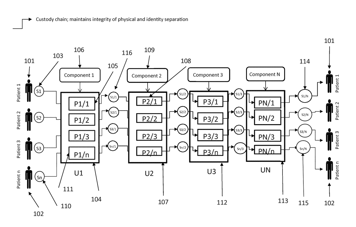
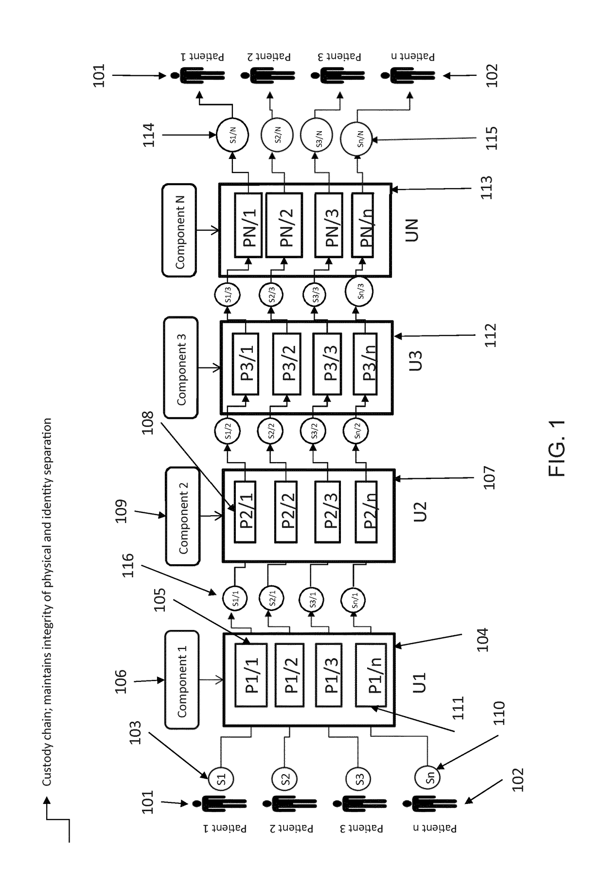
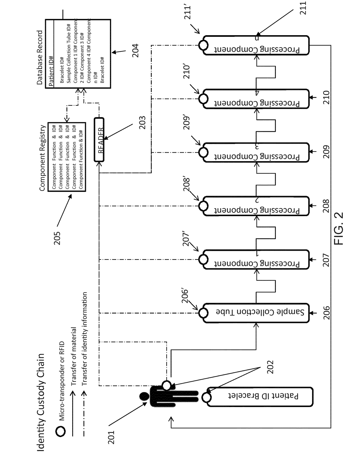
[0017]A scalable cell therapy facility comprises a number of discrete processing units (UNIT 1 to UNIT N) isolated from one another by physical walls, barriers or other demarcation. Each processing unit comprises a number of identical processing stations (P1 / 1 to P1 / n in UNIT 1; P2 / 1 to P2 / n in Unit 2; PN / 1 to PN / n in UNIT N) appropriate for the unique processing operation to be carried out within the unit. Patient samples (S1 to Sn) are received by UNIT 1 in uniquely encoded closed sample containers and processed on processing stations P1 / 1 to P1 / n using a separate uniquely coded closed disposable processing component 1 for each sample. Processed samples in closed components appropriate to the workflow stage are sequentially passed through UNIT2 to UNIT N to complete the processing workflow using uniquely coded closed processing components 2 to N at each stage. At each stage of processing transfer of processed patient material from component to component is tracked by recording com...


PUM


Abstract

The present invention provides improved methods, facilities and systems for parallel processing of biological cellular samples in an efficient and scalable manner. The invention enables parallel processing of biological cellular samples, such as patient samples, in a space and time efficient fashion. Process simulation may be used to determine the optimal arrangement and/or quantity of cell processing equipment needed. The methods, facilities and systems of the invention find particular utility in processing patient samples for use in cell therapy.

Description

BACKGROUND TO THE INVENTION[0001]Cell therapy is a key area of medical advance in the treatment of a range of conditions and diseases including cancer. Autologous cell therapy, the treatment of a patient with the patient's own cells, is an increasingly used and improving method for combatting cancers, including melanoma and leukaemia, which are refractory to conventional drug treatment. One area of autologous cell therapy, immunotherapy, uses selection and expansion of cells from the patient's own immune system to target and attack cancer cells, effectively boosting, many fold, the patient's immune response to destroy the cancer cells.[0002]To achieve immunotherapy and other forms of cell therapy samples of cells taken from a patient, typically in the form of a blood sample, must be processed through a complex workflow to isolate, engineer, concentrate and / or expand by culture the cells which will form the therapeutic material administered back into the patient. Carrying out the cel...

Claims


Application Information

Patent Timeline
Patent Type & Authority Applications(United States)
IPC IPC(8): G06Q10/06G06F19/00
CPCG06Q10/06313G06Q10/0633G06Q10/063118G06F19/366G16H10/40A61P35/00A61P37/04G16H10/60
Inventor BAKSH, DOLORESABKAY, KUNTER SEREFWOOD, NICHOLE LEASMITH, REGINALD DONOVAN
Owner GLOBAL LIFE SCI SOLUTIONS USA LLC
Why Eureka
Try Eureka