Microfluid cell processing chip and application method thereof

A microfluidic chip and processing chip technology, applied in applications, preservation of human or animal bodies, animal husbandry, etc., can solve the problem that the processing accuracy of channels and cavities cannot be well guaranteed, and the complexity of chip processing and proficiency requirements are increased. High and other problems, to achieve the effect of eliminating complexity, maintaining system pressure drop value, and overcoming complex processing technology

Active Publication Date: 2016-08-10
UNIV OF SHANGHAI FOR SCI & TECH
View PDF3 Cites 21 Cited by
  • Summary
  • Abstract
  • Description
  • Claims
  • Application Information

AI Technical Summary

Problems solved by technology

The operation steps of this method are cumbersome, and it is required to accurately find the cells under the microscope in a short period of time and complete the transfer of the cells between the solutions, which is very easy to cause the loss of the cells and requires a high level of proficiency for the operator; And the number of step-by-step removals cannot be increased too much, so that the oocytes will still be subjected to several sudden volume changes due to sudden changes in the concentration of the protective agent, and the exposure time to high concentrations of cryoprotectant is long
[0004] Aiming at the above-mentioned problems existing in the prior art, Chinese Patent Publication No. CN103451090A discloses a microfluidic cell processing chip and its application method. It provides a microfluidic cell processing chip that continuously changes the concentration of cryoprotectant. During the removal process, the cryoprotectant flows into the cell operation chamber after mixing through the serpentine channel, and the cells are loaded or sucked out of the chip through the torque control microvalve above the cell inlet and outlet channels, and the cells are restricted by the half partitions on the left and right sides of the operation chamber. In the cell cavity, although the chip and cell processing method can complete the continuous loading and removal of cryoprotectant for large-volume animal cells, there are still many problems in the production and application: (1) the serpentine channel in the chip, the cell The heights of the three important structures of the operating chamber and the half-partition are not uniform. Therefore, in the photolithography stage of processing, photolithography masks need to be layered and made multiple times, and then different layers are bonded together in the sealing stage, which is not very good. The processing accuracy of the guarantee channel and the cavity increases the production cost; (2) the cell controls the opening and closing of the microvalve through the torque to control the cell entering and exiting the cell operation cavity, and the switch state of the valve is controlled by the screw fixed above the channel of the PDMS chip , the deformation part between the screw end and the fluid channel is a thin layer of polyurethane material. This design requires the coupling of two materials, PDMS and polyurethane, on the chip, which increases the complexity of chip processing. Although this microvalve has a simple structure, it does not require It is a complex control system, but it is difficult to automate in the later stage, and it is only suitable for simple microfluidic systems and laboratory operations; (3) half partitions are used on the left and right sides of the operation chamber to limit cells, and the height of the channel at the half partition can be adjusted according to the cell However, the height of the channel at the semi-partition is significantly smaller than that of the serpentine channel, and the resistance of the liquid flowing through it will increase, and the pressure drop value of the system will increase, which will easily cause damage to the microfluidic chip and shorten the Chip service life

Method used


Image

  • Microfluid cell processing chip and application method thereof
  • Microfluid cell processing chip and application method thereof
  • Microfluid cell processing chip and application method thereof

Examples


Embodiment Construction

[0034] The present invention will be described in further detail and completely below in conjunction with the accompanying drawings and embodiments.

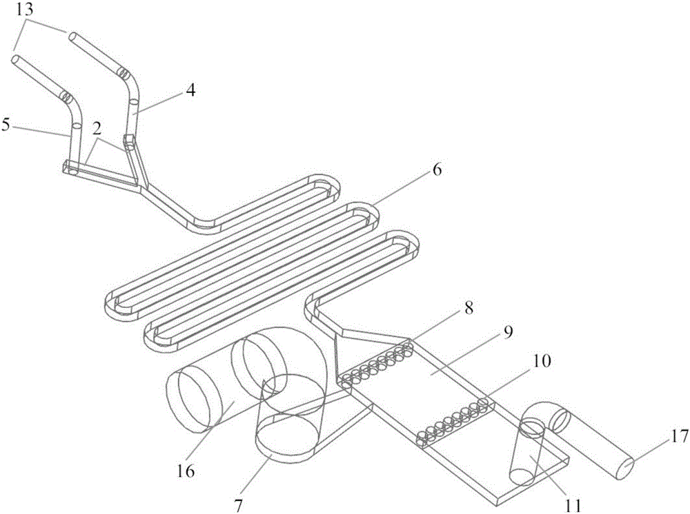
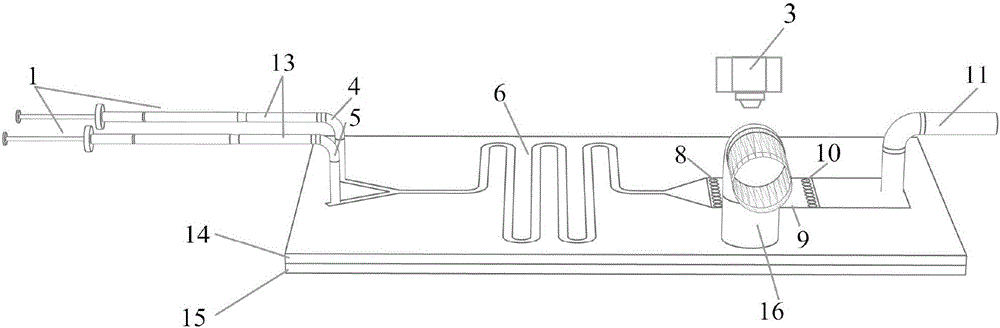
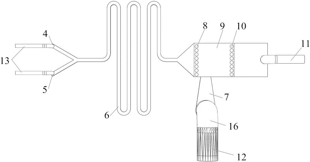
[0035] Such as Figure 1 to Figure 3 As shown, the microfluidic cell processing chip of the present invention consists of a bottom layer 14 and a top layer 15 . The chip body is connected with two dual-channel microinjection pumps through a microfluidic chip capillary, and is installed on the automatic stage of the confocal microscope 3 .

[0036] Such as figure 1 , as shown in 2, the top layer 15 is provided with a serpentine pipeline 6 and a cell operation chamber 9, and the solution inlet of the serpentine pipeline 6 is provided with two inflow passages 2 connected with inlet pipes, and the inlet pipes of the two inflow passages 2 The protective agent inlet 4 and the buffer solution inlet 5 are respectively provided on the top, and the solution outflow channel of the serpentine pipeline 6 is connected to the cell operation ...


PUM


Abstract

The invention relates to a microfluid cell processing chip comprising a bottom layer and a top layer. A snakelike pipe and a cell operation chamber are disposed in the top layer, and two solution inflow channels are disposed on the inflow-port of the snakelike pipe. A protective agent entrance is disposed on the inlet pipe of one of the inflow channels, and a buffer solution entrance is disposed on the inlet pipe of another inflow channel. A solution outflow channel of the snakelike pipe is connected with the cell operation chamber, and the cell operation chamber is provided with a solution exit, a waste fluid outflow channel and a cell access channel. A row of cylindrical barriers are disposed on each side of the cell operation chamber, and the barriers are used for limiting the cell in the operation chamber, so that the cell can not be washed away by the protective agent. In practical application, operator uses the refitted cell mouth-sucking device to blow or suck the cell in or out the chip cell operation chamber directly. The microfluid cell processing chip and application method thereof can make the concentration of protective agent change continuously when adding or removing the cryoprotectant of animal cell with large volume. The method has direct and simple operation, and has less damage for cell.

Description

technical field [0001] The invention relates to a microfluidic cell processing chip, in particular to a microfluidic chip capable of continuously changing the concentration of the cryoprotectant in the process of loading and removing the cryoprotectant with little damage to cells and remarkable ease of operation and its application method. Background technique [0002] Cell cryopreservation is one of the main methods of cell preservation. Using cryopreservation technology to store cells in -196°C liquid nitrogen at low temperature can temporarily remove the cells from the growth state and preserve their cell characteristics, so that the cells can be revived for experiments when needed. Moreover, moderately preserving a certain amount of cells can prevent the cells from being lost due to contamination of the cells being cultured or other accidents, which plays a role in cell preservation. When cells are cryopreserved, add a protective agent to the medium—glycerol or dimethy...

Claims


Application Information

Patent Timeline
Patent Type & Authority Applications(China)
IPC IPC(8): A01N1/02
CPCA01N1/0242
Inventor 周新丽衣星越周楠峰杨云李维杰
Owner UNIV OF SHANGHAI FOR SCI & TECH
Why Eureka
Try Eureka