Eureka AIR delivers breakthrough ideas for toughest innovation challenges, trusted by R&D personnel around the world.

Rechargeable electric power tool

Active Publication Date: 2018-01-11
MAKITA CORP
View PDF19 Cites 7 Cited by
  • Summary
  • Abstract
  • Description
  • Claims
  • Application Information

AI Technical Summary

Benefits of technology

The patent text explains that the gear housing and battery pack are balanced by arranging them back and forth to reduce weight. The handle housing is designed in a loop shape to provide a stable grip, even when the weight is heavy, ensuring excellent operability.

Problems solved by technology

The above-described conventional rechargeable electric power tool is heavy in weight because a front portion having the chuck, the spindle, the deceleration mechanism, and similar parts, and a rear portion on which the two battery packs are mounted are combined.
Thus, it is difficult to operate the conventional rechargeable electric power tool.

Method used


Image

  • Rechargeable electric power tool
  • Rechargeable electric power tool
  • Rechargeable electric power tool

Examples


Embodiment Construction

[0035]The following describes an embodiment of this disclosure based on the drawings.

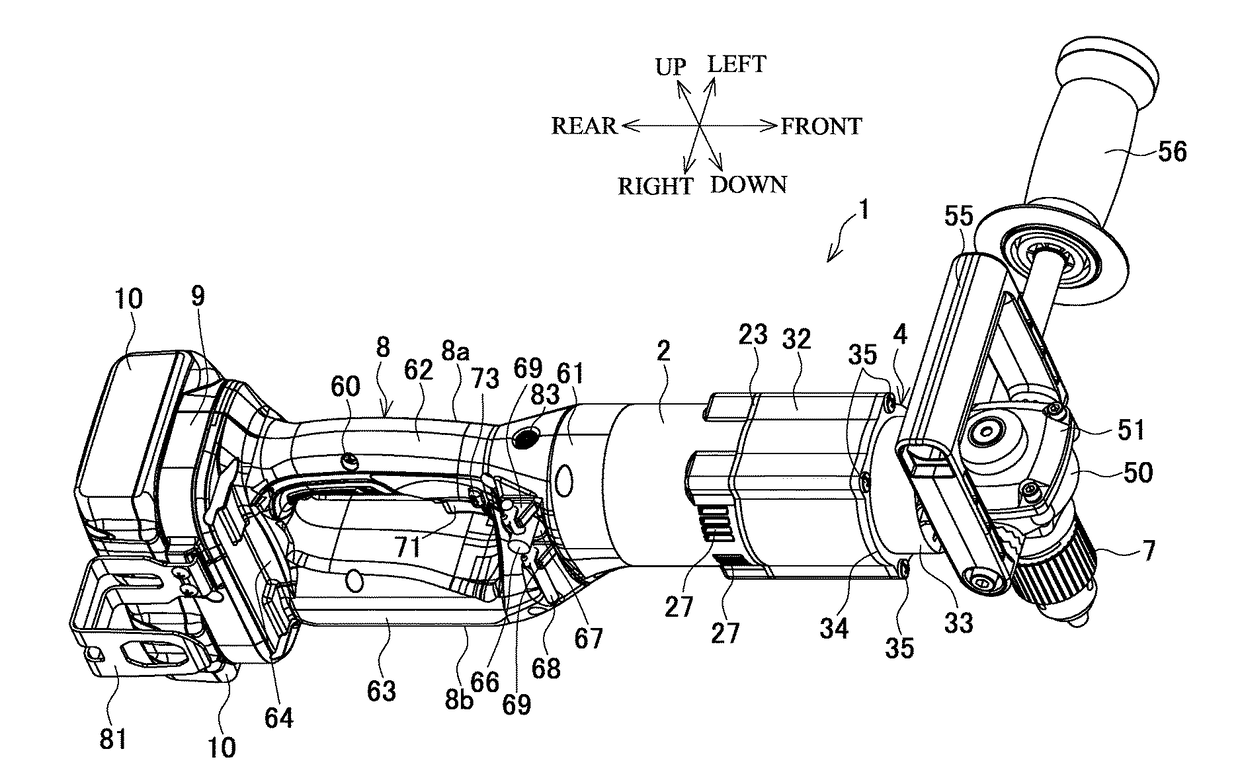
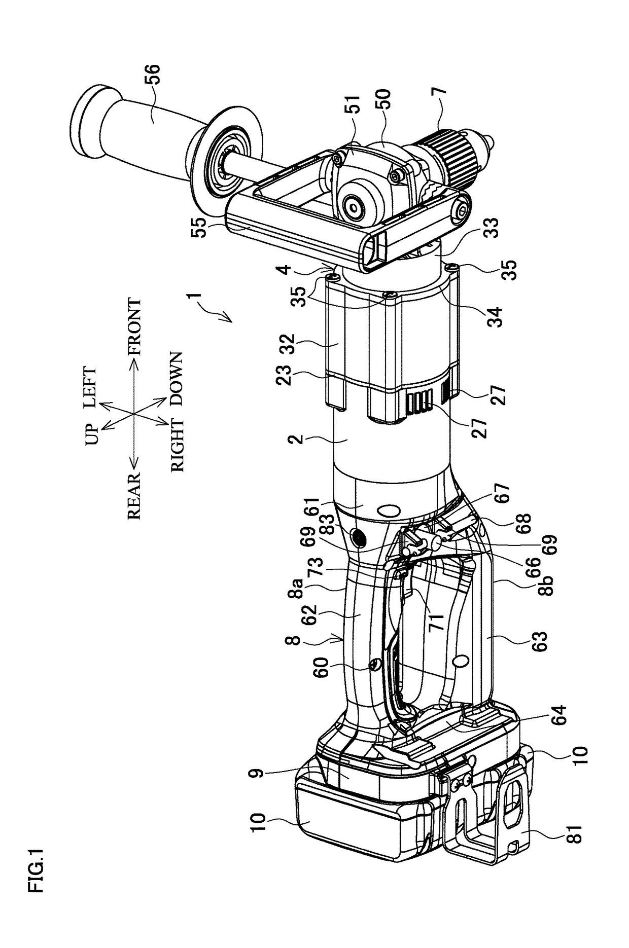
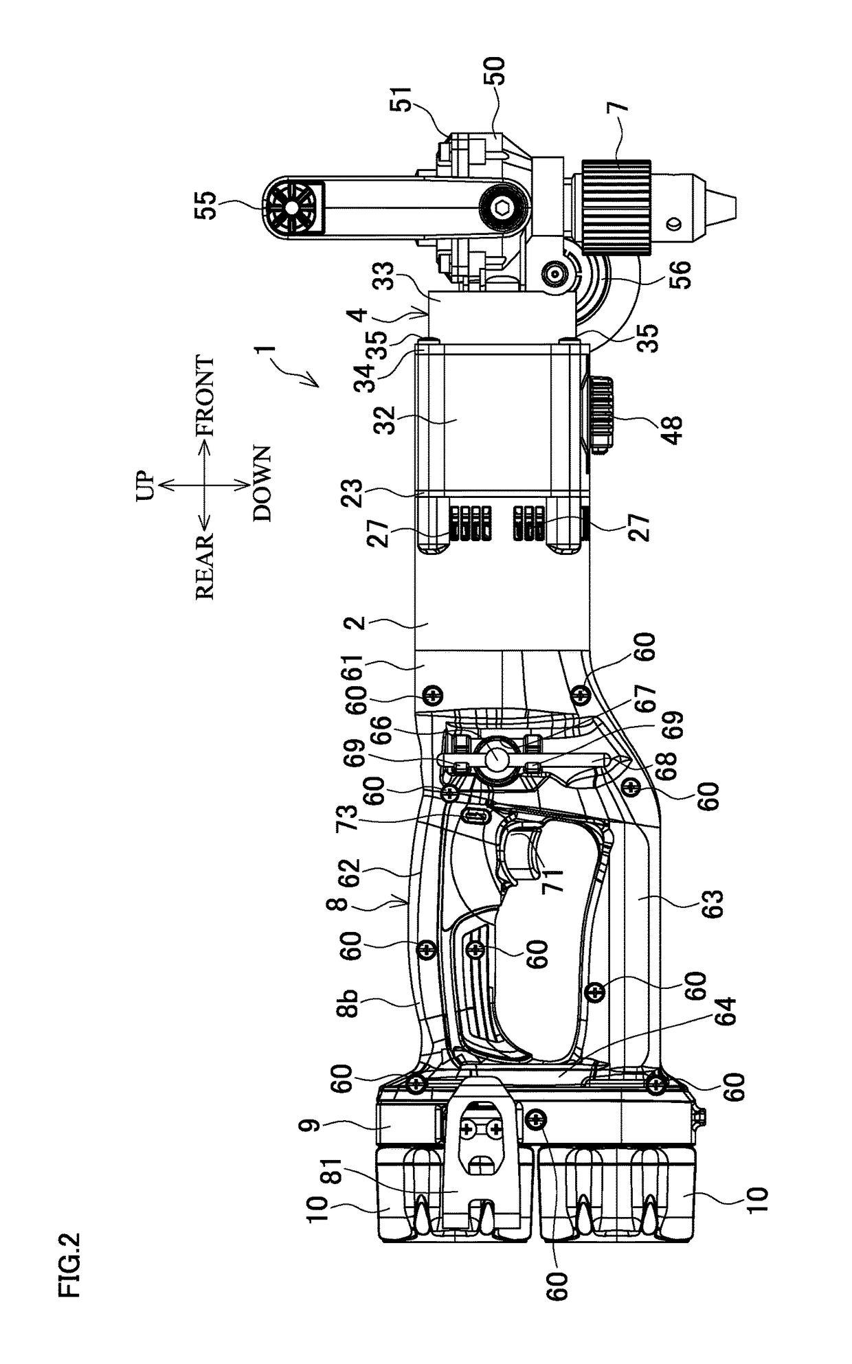
[0036]FIG. 1 is a perspective view of a rechargeable angle drill, which is an exemplary rechargeable electric power tool, FIG. 2 is its right side view, FIG. 3 is its plan view, FIG. 4 is its bottom view, and FIG. 5 is its front view. FIG. 6 is vertical cross-sectional view taken along the line A-A. FIG. 7 is a cross-sectional view taken along the line B-B.

[0037]In the rechargeable angle drill (hereinafter referred to as simply an “angle drill”) 1 shown in FIGS. 1 to 7, a front of a motor housing 2 is coaxially coupled to a gear housing 4. The gear housing 4 is made of metal (e.g. Aluminum) and houses a deceleration mechanism 5, and the motor housing 2 is made of resin and houses a brushless motor 3. In a front portion of the gear housing 4, a spindle 6 is downwardly housed. The spindle 6, as a final output shaft, mounts a drill chuck 7 on its lower end. On the other hand, a rear of the motor housin...


PUM


Abstract

A rechargeable electric power tool includes a motor that includes a rotation shaft, a motor housing that houses the motor, a gear housing disposed ahead of the motor, a final output shaft that is held onto the gear housing and perpendicular to the rotation shaft, and a loop-shaped handle housing disposed at a rear of the motor housing, and a battery mounting portion configured to hold two battery packs is disposed at a rear portion of the handle housing.

Description

BACKGROUND[0001]This application claims the benefit of Japanese Patent Application Number 2016-133571 filed on Jul. 5, 2016, the entirety of which is incorporated by reference.TECHNICAL FIELD[0002]The disclosure relates to a rechargeable electric power tool such as an angle drill using a battery pack as a power source.RELATED ART[0003]As disclosed in Japanese Patent Application Publication No. 2014-148021 (JP-A-2014-148021), there has been known a rechargeable electric power tool that includes a battery pack, as a power source, at a battery mounting portion disposed in a housing. JP-A-2014-148021 exemplifies an angle drill where a motor is disposed in a middle portion of the tubular housing that extends in a front-rear direction, and a spindle having a chuck is downwardly disposed at its front portion, so as to allow rotation of an output shaft of the motor to transmit to the spindle via a deceleration mechanism such as a bevel gear. A battery base (battery mounting portion) is disp...

Claims


Application Information

Patent Timeline
IPC IPC(8): B25F5/02B25F5/00
CPCB25F5/02B25F5/026B25F5/008B25F5/00B25F5/001
Inventor NAGASAKA, HIDENORIIMAE, TOMOHIKO
Owner MAKITA CORP
Why Eureka
Eureka Blog
Learn More