System and method for supplying uninterruptible power to a poe device in a powered state

a technology of uninterruptible power and poe device, which is applied in emergency power supply arrangements, data switching details, data switching networks, etc., can solve the problem that the system still supplies uninterrupted power to both powered devices

Active Publication Date: 2018-01-11
BTU RES LLC
View PDF1 Cites 11 Cited by
  • Summary
  • Abstract
  • Description
  • Claims
  • Application Information

AI Technical Summary

Benefits of technology

[0026]Embodiments of the present invention include a system for supplying uninterruptible power for a Power over Ethernet (PoE) device. In embodiments of the present invention, the system includes a housing, a power supply input on the housing, a power source equipment input on the housing, a powered device output on the housing, an alternative power supply within the housing, an

Problems solved by technology

In this embodiment, the system still supplies uninterrupted power to both

Method used


Image

  • System and method for supplying uninterruptible power to a poe device in a powered state
  • System and method for supplying uninterruptible power to a poe device in a powered state
  • System and method for supplying uninterruptible power to a poe device in a powered state

Examples


Embodiment Construction

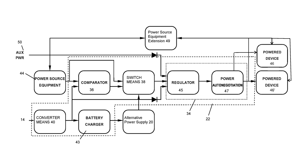
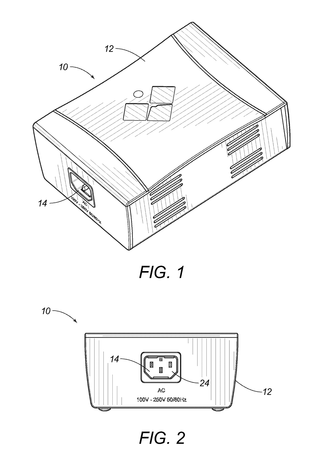
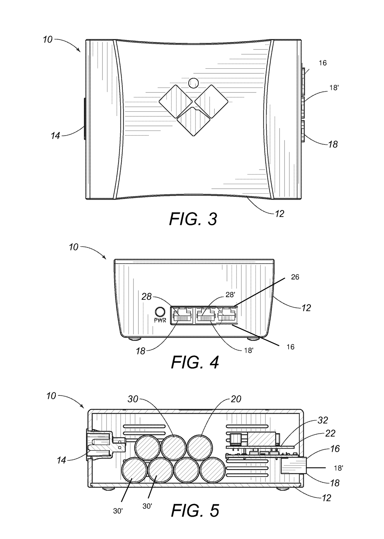
[0034]Referring to FIGS. 1-6, embodiments of the system 10 for supplying uninterruptible power are shown. The system 10 includes a housing 12, a power supply input 14, a power source equipment input 16, a first powered device output 18, a second powered device output 18′, an alternative power supply 20, and a control module 22. FIGS. 1-4 show the housing 12 as a separate unit for placement at a location of the powered device or PoE device. The PoE device is remotely located from a control center of the overall network of PoE devices, and the power source for the control center is separate from each PoE device. The PoE device relies on the data transmission back and forth through the network from the control center. The only power from the control center or from intervening power source equipment is transmitted by Ethernet cabling. Because of the physical restraints of Ethernet cabling, not much power is transmitted to the system 10. The Ethernet cabling engages the power source equi...


PUM


Abstract

A system and method for supplying uninterruptible power includes a housing, a power supply input, a power source equipment input, a first powered device output, a second powered device output, an alternative power supply, and a control module. The control module includes a comparator, a switch, a converter and an injector. The injector includes a regulator and power autonegotiation module. The alternative power supply includes a plurality of battery packs in series. There can also be first and second powered devices with uninterrupted power, even when only one of the powered devices breaks. A power is uninterrupted to the first powered device, even if power is stopped to the second powered device, due to a repair or fault of the second powered device.

Description

CROSS-REFERENCE TO RELATED APPLICATIONS[0001]See Application Data Sheet.STATEMENT REGARDING FEDERALLY SPONSORED RESEARCH OR DEVELOPMENT[0002]Not applicable.THE NAMES OF PARTIES TO A JOINT RESEARCH AGREEMENT[0003]Not applicable.INCORPORATION-BY-REFERENCE OF MATERIAL SUBMITTED ON A COMPACT DISC OR AS A TEXT FILE VIA THE OFFICE ELECTRONIC FILING SYSTEM (EFS-WEB)[0004]Not applicable.STATEMENT REGARDING PRIOR DISCLOSURES BY THE INVENTOR OR A JOINT INVENTOR[0005]Not applicable.BACKGROUND OF THE INVENTION1. Field of the Invention[0006]The present invention relates to system and method for supplying uninterruptible power to a Power-over-Ethernet (PoE) device. More particularly, the present invention relates to a system with an active injector connected to a power supply input, an alternative power supply, and a power source equipment input as the PoE power. The present invention relates to a method for controlling an uninterrupted power supply in a powered state.2. Description of Related Ar...

Claims


Application Information

Patent Timeline
IPC IPC(8): H02J9/06H02J7/00H04L12/10
CPCH02J9/061H02J7/0024H02J7/007H04L12/10H02J9/00H04L12/413H02J7/007182
Inventor KANARELLIS, MICHAELMCANDREW, CHARLES I.
Owner BTU RES LLC
Why Eureka
Try Eureka