
Ankle ergometer

Active Publication Date: 2018-01-18
UNIV DE VALENCIENNES & DU HAINAUT CAMBRESIS +1
View PDF1 Cites 0 Cited by
  • Summary
  • Abstract
  • Description
  • Claims
  • Application Information

AI Technical Summary

Benefits of technology

The present invention proposes an ergometer that can accurately measure the forces exerted at the joint of the ankle by the flexor muscles of the foot, without being impacted by other muscles such as the hip or knee extensor muscles. This results in a reliable and accurate measurement, and offers a remedy to the limitations of other ergometers currently available.

Problems solved by technology

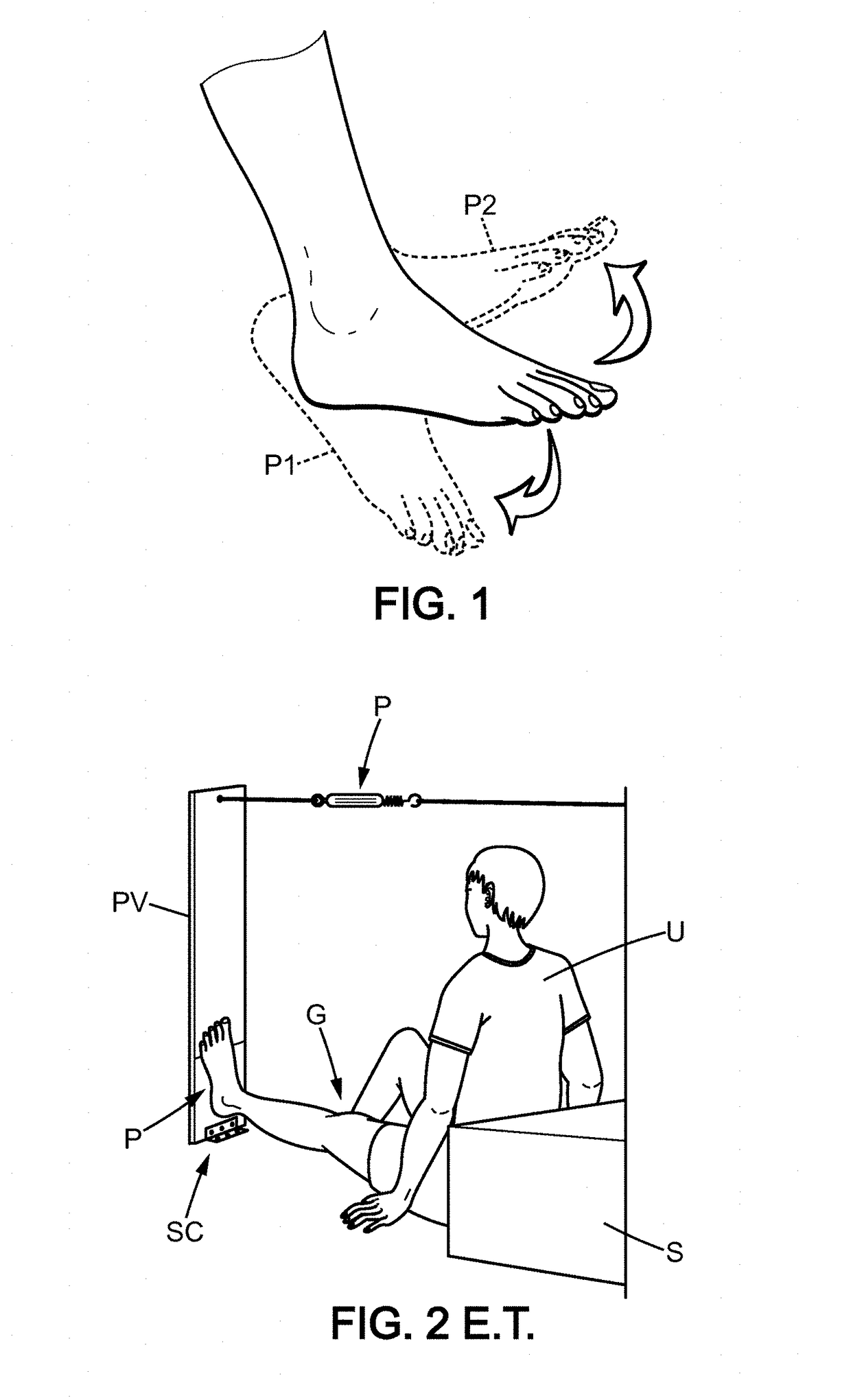
Such a system only allows measurement of the forces exerted during plantar flexion (or extension), and does not allow measurement of the forces exerted during a dorsal flexion (or dorsiflexion).
The Applicant however submits that the whole of the existing ergometers of ankle type have many limits and many drawbacks.
This necessarily implies the mobilization of muscles of other joints, which causes an overestimation of the evaluation of the forces or of the force moments developed at the ankle and may also cause strong variability of the measurements.
This is due to the fact that with the present ergometers, the user may stress other muscles during the effort for achieving plantar flexion, for example the extensor muscles of the knee or of the hip: the configuration of the present ergometers therefore implies an error which is difficult to detect so that it is impossible to correct them a posteriori.
The existing ergometers do not give the possibility of evaluating the whole of the exerted stresses at the joint of the ankle.
The use of a unidirectional sensor exclusively gives the possibility of determining what occurs around the transverse axis of the ankle; such a sensor does not give the possibility of evaluating the accessory moments to the plantar flexion, i.e. those around sagittal (or longitudinal) and vertical axes of the ankle (in inversion and in adduction).
Finally, the Applicant observes that the existing ergometers are often very bulky and difficult to displace; moreover, the existing ergometers can only be used on a single leg at a time and cannot be easily used in a bedridden position.

Method used


Image

  • Ankle ergometer
  • Ankle ergometer
  • Ankle ergometer

Examples


Embodiment Construction

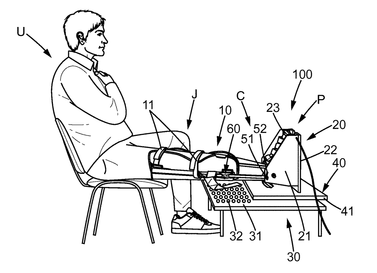
[0120]An ergometer according to an exemplary embodiment of the present invention will now be described in the following by referring jointly to FIGS. 4 to 6.

[0121]As a reminder, during the isometric contraction of the muscles of the ankle towards the extension, it is noted on most ergometers of the state of the art that the user uses the support of his / her back or of his / her shoulders for pushing on the pedal of the ergometer, which involves a participation of other muscles on other joints inducing an overestimation of the evaluation of the forces (or force moments) developed on the joint of the ankle.

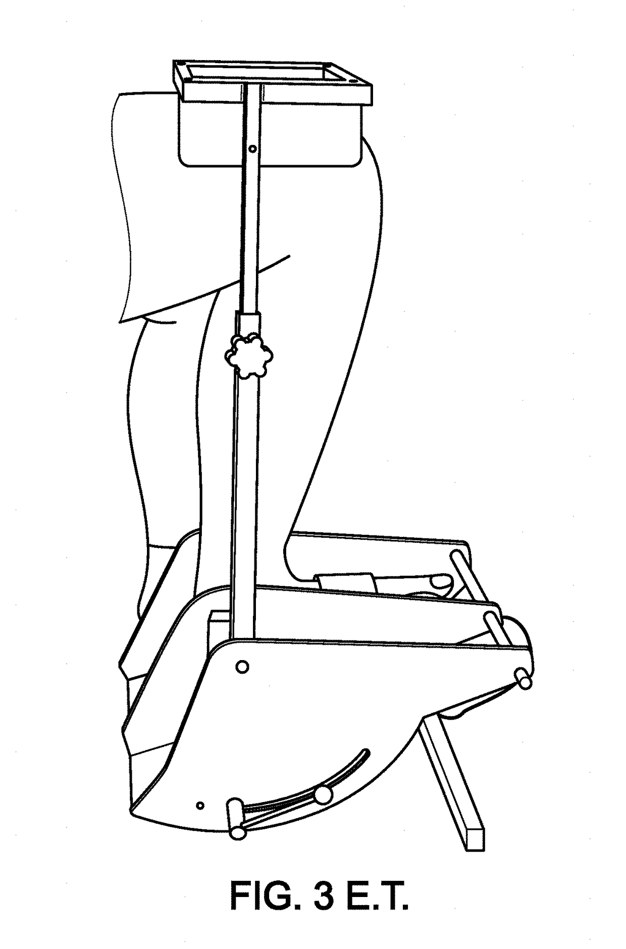
[0122]It is also observed that the ergometers of the ankle type which position the user in the sitting position, with the knee bent to 90° in order to limit the participation of the joint of the knee, reducing the forces of the gastrocnemius muscles.

[0123]Now, it is important to evaluate the forces developed by these gastrocnemius muscles on the ankle.

[0124]It is therefore preferable t...


PUM


Abstract

Disclosed is an ankle ergometer for measuring a force exerted on a user's ankle joint by muscles involved in ankle mobility, including: a first splint-type portion receiving the lower limb when the user's knee is extended, and including a lower limb immobilizer with the leg in extension, and a second portion including: a) a main body attached to the first portion, b) a counter-supporting unit secured to the main body, c) a rigid plate forming a supporting surface for the lower surface of the foot, the rigid plate being substantially static relative to the counter-supporting unit, d) a force sensor between the plate and the counter-supporting unit, the plate not being secured to the main body so the sensor measures the force exerted on the supporting surface of the plate by the ankle mobility muscles, the force being transmitted from the plate to the counter-supporting unit.

Description

TECHNICAL FIELD AND PRIOR ART[0001]The present invention relates to the field of ergometers, and more particularly that of ankle type ergometers.[0002]One of the objects of the present invention is to provide a measurement apparatus able to measure with accuracy the mechanical properties of muscles of the ankle, and notably the capability of the muscles involved in the mobility of the ankle, and more particularly the capability of the muscles of the ankle of exerting a force for achieving plantar flexion (or extension) and / or dorsal flexion (or dorsiflexion).[0003]The present invention finds many advantageous applications in the medical and / or paramedical field or further in the sports field for example during physical preparation.[0004]As an example mention may be made of applications of the present invention, the conduction of tests on a person in order to evaluate his / her capability of maintaining an orthostatic posture (standing position); this is for example particularly advant...

Claims


Application Information

Patent Timeline
IPC IPC(8): A61B5/00A61B5/22
CPCA61B5/4595A61B5/221A61B5/4519A61B5/6828A61B5/6829A61B5/702A61B5/1107A61B5/1124A61B5/224A61B5/4023
Inventor SIMONEAU-BUESSINGER, EMILIEGILLET, CHRISTOPHELETENEUR, SEBASTIENDEBRIL, JEAN-FRANCOISDECOUFOUR, NICOLAS
Owner UNIV DE VALENCIENNES & DU HAINAUT CAMBRESIS
Learn More