
Atomizing device

a technology of atomizer and atomizer, which is applied in the direction of air humidification system, heating type, lighting and heating apparatus, etc., can solve the problem of increasing the risk of malfunction

Active Publication Date: 2018-02-01
TAIWAN PURITIC
View PDF1 Cites 2 Cited by
  • Summary
  • Abstract
  • Description
  • Claims
  • Application Information

AI Technical Summary

Benefits of technology

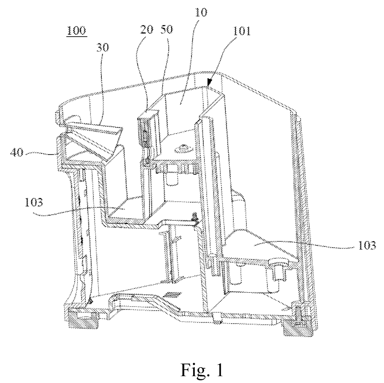
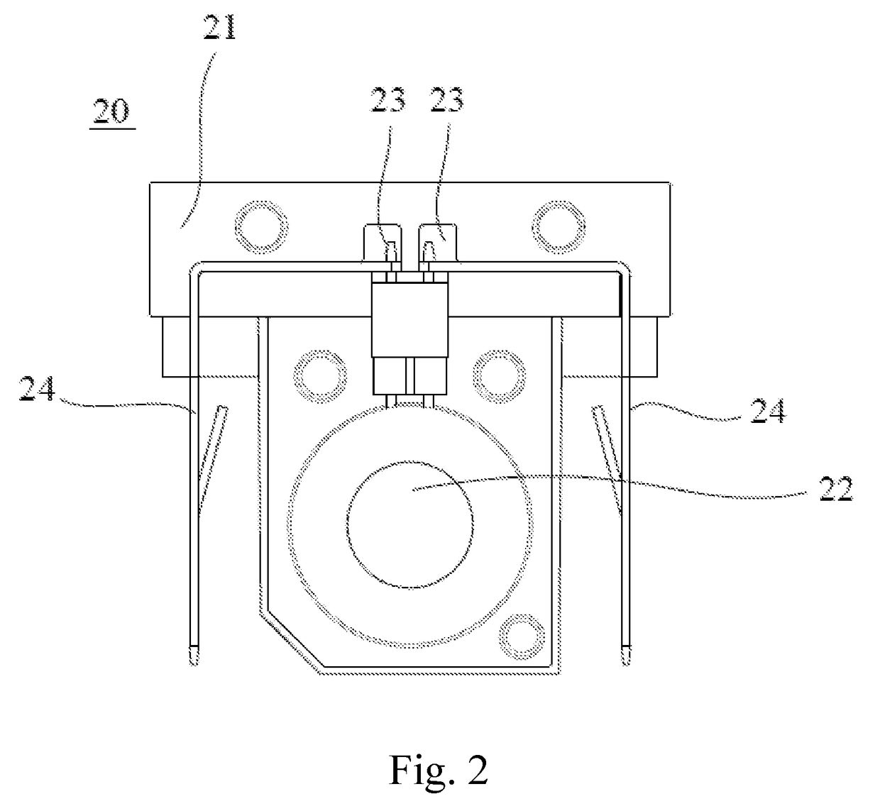
The invention is an atomizing device that sprays liquid into small droplets. It has a chamber with a nozzle plate to create the droplets and a channel-like structure to allow the droplets to bounce and form second droplets. These second droplets can then be sprayed out. The device has a droplet inlet that is larger than its droplet outlet, and the channel-like structure has surfaces that the droplets can bounce off repeatedly. The device can have a second liquid storage chamber and interconnection unit to allow the droplets to flow back and forth. The nozzle plate can be easily installed and has electric-conduction contacts for connection to external contacts. The technical effects of this invention include improved spraying of liquids into small droplets.

Problems solved by technology

The heat generated by oscillation may overheat the machine and increase the risk of malfunction.

Method used


Image

  • Atomizing device
  • Atomizing device
  • Atomizing device

Examples


Embodiment Construction

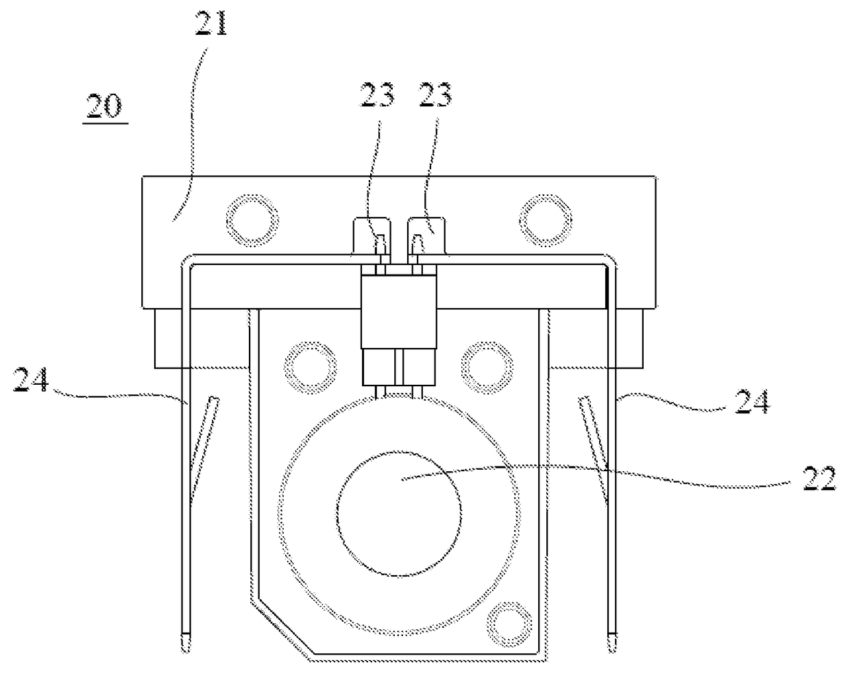
[0021]The present invention will be described in detail with embodiments and attached drawings below. However, these embodiments are only to exemplify the present invention but not to limit the scope of the present invention. In addition to the embodiments described in the specification, the present invention also applies to other embodiments. Further, any modification, variation, or substitution, which can be easily made by the persons skilled in that art according to the embodiment of the present invention, is to be also included within the scope of the present invention, which is based on the claims stated below. Although many special details are provided herein to make the readers more fully understand the present invention, the present invention can still be practiced under a condition that these special details are partially or completely omitted. Besides, the elements or steps, which are well known by the persons skilled in the art, are not described herein lest the present i...


PUM


Abstract

The present invention provides an atomizing device, which comprises: a first liquid chamber to store a liquid to be atomized; a nozzle plate unit disposed on the first liquid chamber and used to spray the liquid into first atomized droplets; and an indirect spray unit disposed at a position where the first atomized droplets are sprayed to accept the first atomized droplets. The indirect spray unit comprises a channel-like structure having a droplet inlet disposed toward a position where the nozzle plate unit sprays out the first atomized droplets; and a droplet outlet disposed on one side wall of the atomizing device. The droplet inlet receives the first atomized droplets to enter the indirect spray unit. The first atomizing droplets undertake striking and rebounding repeatedly in the channel-like structure to form the second atomized droplets. The second atomized droplets are sprayed out from the droplet outlet.

Description

BACKGROUND OF THE INVENTION1. Field of the Invention[0001]The present invention relates to an atomizing device, particularly to an atomizing device having an indirect spray unit.2. Description of the Prior Art[0002]A desktop air humidifier is usually used in a dry climate, atomizing the liquid of the humidifier into droplets to increase the humidity of the air. Generally speaking, the liquid should be atomized into droplets having a smaller diameter lest the air be over-humidified by larger droplets. In the conventional technology, a high-frequency oscillation plate undertakes high-frequency oscillations in a liquid to atomize the liquid. The heat generated by oscillation may overheat the machine and increase the risk of malfunction. If the liquid has additives, such as essences, flagrances, etc., heat may denature the additives.[0003]Therefore, it is necessary for the manufacturers to provide an atomizing device able to atomize liquid into droplets having a smaller diameter without...

Claims


Application Information

Patent Timeline
Patent Type & Authority Applications(United States)
IPC IPC(8): B05B17/06F24F6/14
CPCF24F6/14B05B17/0653B05B7/0012B05B17/0607B05B17/0646F24F2006/008B05B14/00Y02B30/54Y02P70/10
Inventor CHIANG, CHUN-TAI
Owner TAIWAN PURITIC
Learn More