Transfer apparatus and transfer method
a transfer apparatus and transfer method technology, applied in the field of transfer techniques, can solve the problems of difficulty in satisfactorily transferring an object, and similar problems do not occur
- Summary
- Abstract
- Description
- Claims
- Application Information
AI Technical Summary
Benefits of technology
Problems solved by technology
Method used
Image
Examples
first embodiment
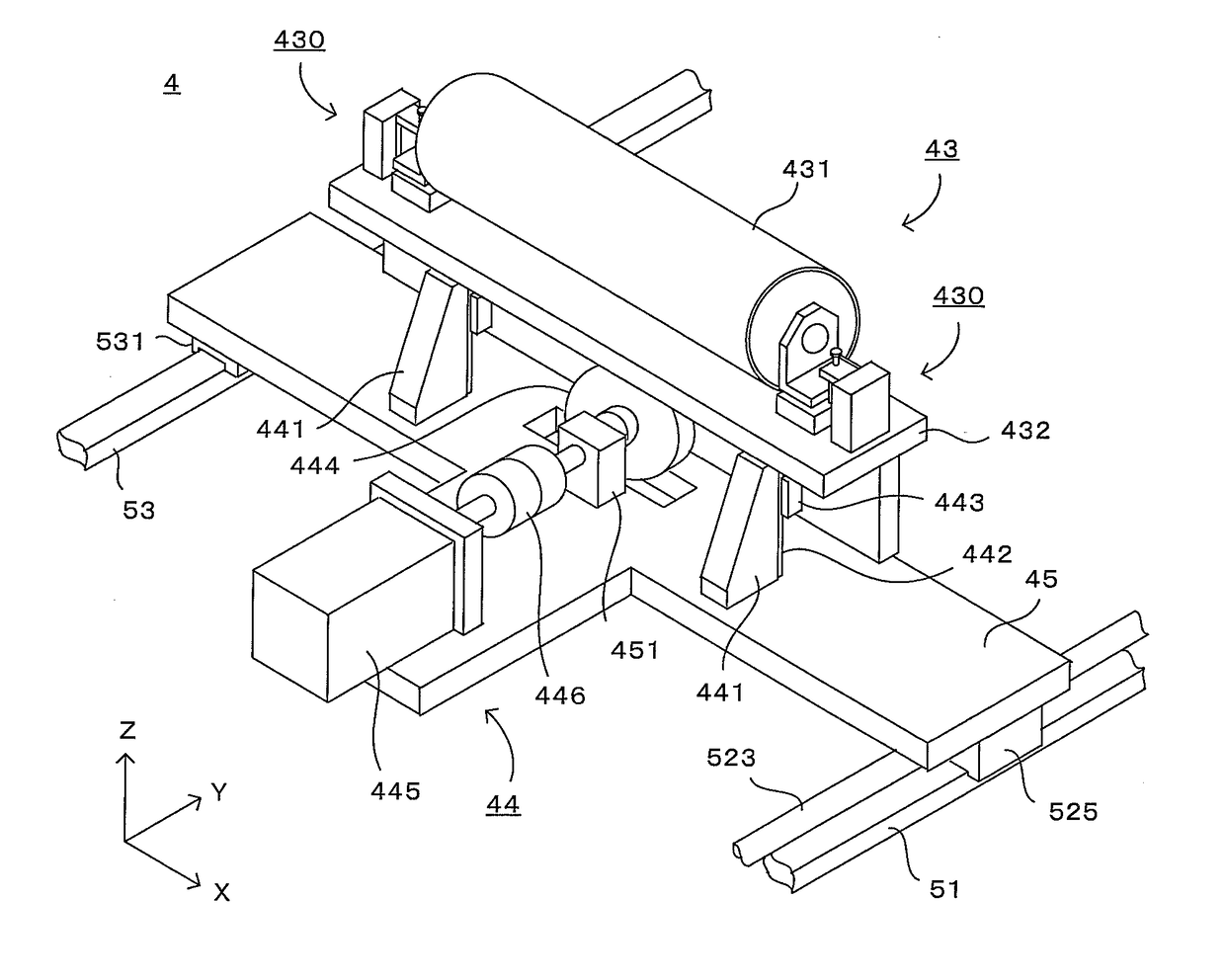
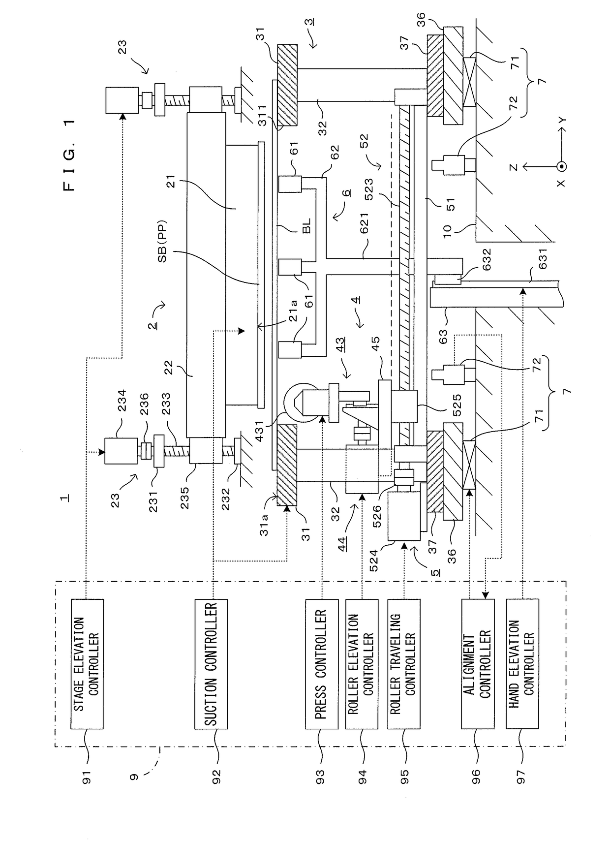
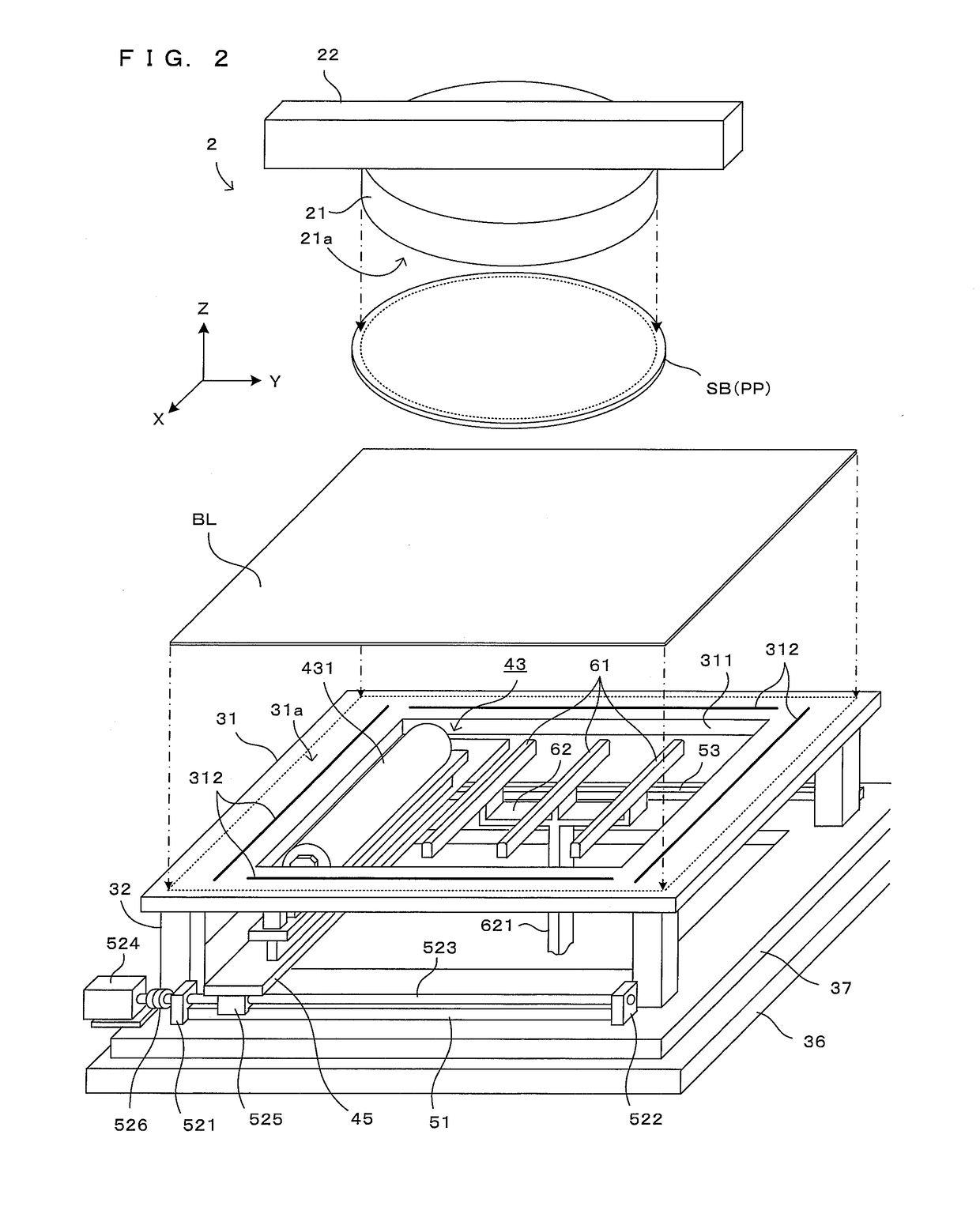
[0024]FIG. 1 is a side view schematically showing a transfer apparatus according to this invention. Further, FIG. 2 is a diagram showing the configuration of a main part of this transfer apparatus. XYZ orthogonal coordinate axes are set as shown in FIG. 1 to comprehensively show directions in each figure. Here, an XY plane represents a horizontal plane. Further, a Z axis represents a vertical axis, more specifically, a (−Z) direction represents a vertically downward direction.
[0025]This transfer apparatus 1 is structured such that an upper stage block 2, a lower stage block 3, a transfer roller block 4, a roller travel driver 5, a supporting hand unit 6 and an alignment unit 7 are arranged on a main frame 10. Further, besides the above, the transfer apparatus 1 includes a control unit 9 for performing a predetermined operation by controlling each component of the apparatus in accordance with a processing program stored in advance.
[0026]First, the overall configuration of the transfe...
second embodiment
[0075]In the second embodiment, a contact area where the substrate SB or the like and a blanket BL are in contact by pressing by the transfer roller 431 is constant regardless of the position of the transfer roller 431. Thus, the biasing forces need not be controlled according to the contact area. However, since the blanket BL is sucked and held by suction grooves 312, bending rigidity of the blanket BL is relatively high when the transfer roller 431 is located at a transfer start position or a transfer end position if distances between the suction grooves 312 and the transfer start position and the transfer end position are short as shown in FIG. 11. Here, “bending rigidity” means the rigidity of the blanket BL against a pressing force generated by the biasing of the transfer roller 431, i.e. difficulty to deform, the bending rigidity suddenly increases as the above distances become shorter, and a profile as shown in a graph (b) in FIG. 11 is developed in the transfer apparatus 1. ...
third embodiment
[0081]Further, the contact state may change depending on a pattern as an object to be transferred. For example, a transfer amount of a pattern forming material may vary depending on the type of the pattern and it is desirable to set suitable biasing forces according to that variation. For example, as shown in FIG. 12, pattern elements PT1 to PT3 having mutually different transfer amounts may be included. Here, the transfer amount of the pattern elements PT1 is largest, and the transfer amount becomes smaller in the order of the pattern elements PT2 and PT3. Thus, if the transfer roller 431 is biased with constant biasing forces, the pressing force per unit area may change according to the Y-direction position of the transfer roller 431. For example, in an area where the transfer amount is large such as the pattern element PT1, the pressing force per unit area is insufficient and a sufficient transfer is not performed. Conversely, in an area where the transfer amount is small such as...
PUM
 Abstract
Description
Claims
Application Information
 - R&D
- Intellectual Property
- Life Sciences
- Materials
- Tech Scout
- Unparalleled Data Quality
- Higher Quality Content
- 60% Fewer Hallucinations
Browse by: Latest US Patents, China's latest patents, Technical Efficacy Thesaurus, Application Domain, Technology Topic, Popular Technical Reports.
© 2025 PatSnap. All rights reserved.Legal|Privacy policy|Modern Slavery Act Transparency Statement|Sitemap|About US| Contact US: help@patsnap.com


