Multi-array camera imaging system and method therefor

a camera imaging and camera technology, applied in the field of imaging, can solve the problems of inability to fully stitch images in the prior-art multi-sensor array imaging approach to display devices, inability to achieve full stitching images, and inability to achieve the effect of delivering large amounts of raw pixel data between imagers and display devices, and achieving fast imaging systems. , the effect of overcoming latency and bandwidth problems

Active Publication Date: 2018-02-01
AQUETI INC
View PDF2 Cites 3 Cited by
  • Summary
  • Abstract
  • Description
  • Claims
  • Application Information

AI Technical Summary

Benefits of technology

[0014]The present invention overcomes the latency and bandwidth problems of prior-art high-pixel-count imaging systems by processing only that pixel data required to render a particular view of interest. Since the viewing device is typically of much lower resolution than the final stitched image, the entire high-resolution image is not formed unless the image needs to be printed. For video-rate capture and display this is critical as the processing of the full-resolution image at video-rate would be prohibitively complex and costly. As a result, embodiments of the present invention enable faster imaging systems that are suitable for video-rate applications.
[0015]In addition, embodiments of the present invention use a captured set of images of a scene to calibrate each imager in a multi-imager system. Subsequent composite images of the scene are then formed with little or no latency by using a model derived from this calibration. In some embodiments, each image pixel in the composite image is drawn from one specific measured pixel in the system. In other words, the image data point that corresponds to each object point in the scene is taken from only one imager (e.g., from the best available imager that covers that image point), thereby avoiding the need to average image data points provided by multiple imagers having overlapping fields of view. The reduced computation time makes real-time operation of the imaging system possible.
[0016]An embodiment of the present invention is an imaging approach wherein the imaging system has a tree hierarchy, which affords scalability of architecture and of image processing. In this approach, only pixel data required to render the view of interest is processed, which enables very low latency thereby enabling interactive viewing of large image-data sets and video-rate capture, as well as rendering of very large pixel counts. Further, pixel capture, processing, and storage is distributed, allowing parallel architectures to be realized using low-cost components.
[0017]In some embodiments, low-latency interactive display of high-pixel-count data sets from a plurality of sensor arrays is enabled.
[0018]The flexible processing architecture of the present invention enables different applications to be served from the same underlying imaging system architecture.

Problems solved by technology

In the prior art, methods for stitching multiple sub-images into a single composite image require significant processing effort, which results in latencies that are not commensurate with video-rate applications.
In other words, prior-art approaches to multi-sensor-array imaging cannot deliver fully stitched images to displays at video rates because of the amount of time it requires to merge the sub-images provided by the different sensor arrays.
Further, the bandwidth requirement for transmitting large amounts of raw pixel-data between the imagers and the display devices would be prohibitive in its own right.
For video-rate capture and display this is critical as the processing of the full-resolution image at video-rate would be prohibitively complex and costly.

Method used


Image

  • Multi-array camera imaging system and method therefor
  • Multi-array camera imaging system and method therefor
  • Multi-array camera imaging system and method therefor

Examples


Embodiment Construction

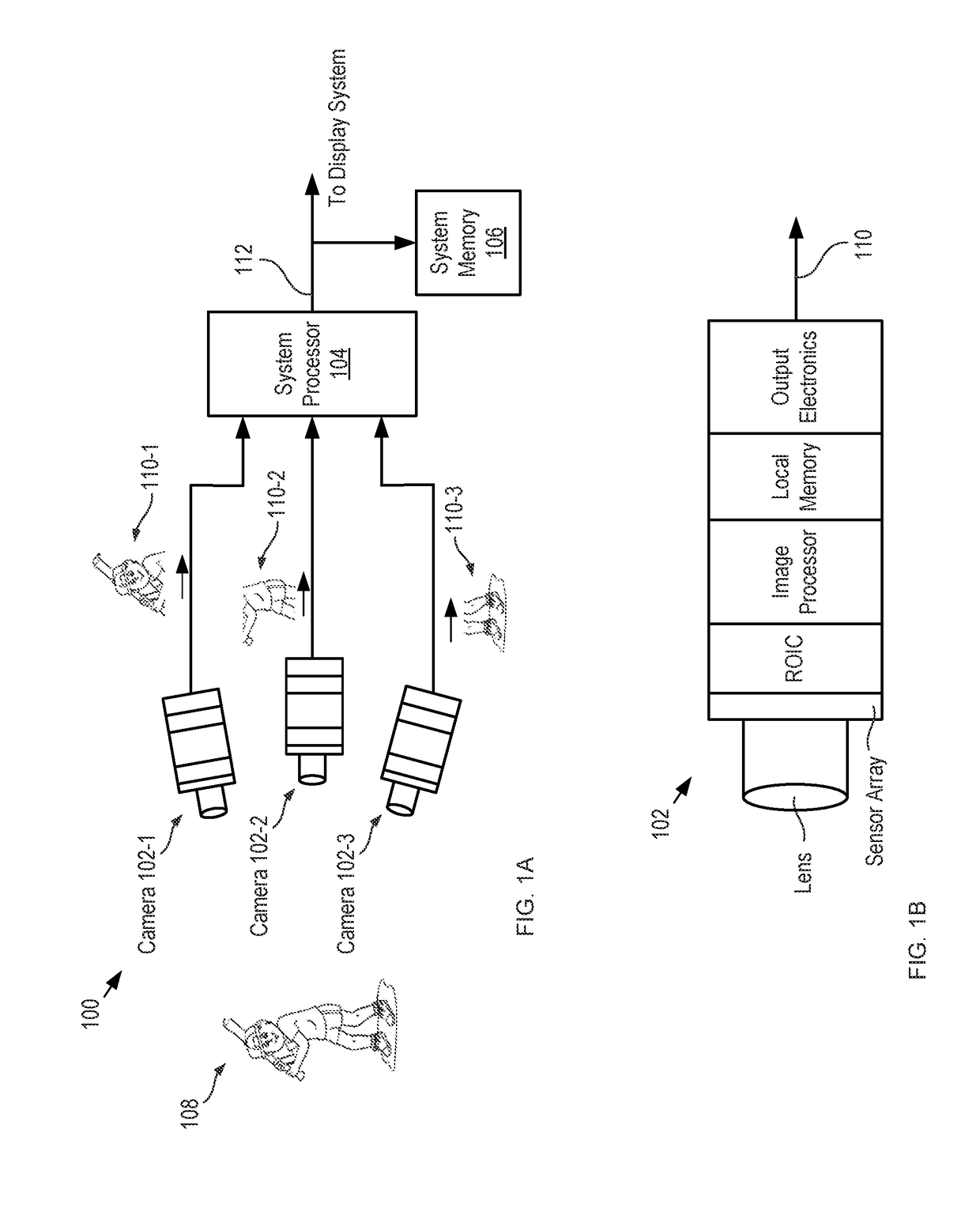
[0026]FIG. 1A-B depict schematic drawings of a conventional array camera and an individual microcamera of the array, respectively. Array camera 100 includes a plurality of microcameras 102-1 through 102-3, system processor 104, and system memory 106. Array camera 100 is representative of typical prior-art multi-sensor-array cameras wherein the sensor arrays reside in individual microcameras.

[0027]Each of microcameras 102-1 through 102-3 (referred to, collectively, as microcameras 102) is a conventional digital video camera that includes independent sensor arrays, image processing capability and memory. Each of microcameras 102 comprises an objective lens, sensor array, read-out integrated circuit (ROIC), image processor, local memory, and output electronics. Microcameras 102 are arranged such that each microcamera provides a video stream of a different portion of scene 108.

[0028]In each video frame of the video stream, the objective lens of each of microcameras 102 forms an optical ...


PUM


Abstract

An imaging system and method for enabling the capture and rendering of an image without the latency and bandwidth requirements of the prior art is presented. Embodiments of the present invention employ a plurality of imagers that provide image data to a plurality of capture and hosting servers to which they are connected via a first communications bus. One or more rendering systems are interconnected to the plurality of servers via a second communications bus. The servers perform parallel processing of only raw image data necessary to satisfy individual rendering requests from the rendering systems. Since image processing is performed only on the image data required to render the particular view of interest, an entire high-resolution image is not formed to satisfy the rendering request and the desired image can be rendered with less latency and requires less bandwidth for transmission to the rendering system.

Description

CROSS REFERENCE TO RELATED APPLICATIONS[0001]This case claims priority of U.S. Provisional Patent Application Ser. No. 62 / 132,861, filed Mar. 13, 2015 (Attorney Docket: 3034-003PR1), which is incorporated by reference. If there are any contradictions or inconsistencies in language between this application and one or more of the cases that have been incorporated by reference that might affect the interpretation of the claims in this case, the claims in this case should be interpreted to be consistent with the language in this case.FIELD OF THE INVENTION[0002]The present invention relates to imaging in general, and, more particularly, to forming images with camera systems having a plurality of focal-plane arrays.BACKGROUND OF THE INVENTION[0003]Prior to the development of digital imaging systems, cameras were based on a lens and a film-based a photographic emulsion located at the focal plane of the lens. An optical image of a scene would be projected onto the emulsion, which would per...

Claims


Application Information

Patent Timeline
Patent Type & Authority Applications(United States)
IPC IPC(8): H04N5/225G06T3/40G06T7/00H04N5/232G06T7/80
CPCH04N5/2258H04N5/23206G06T7/80G06T7/97G06T3/4038G06T15/205H04N23/54H04N23/661H04N23/951H04N23/80G06T1/0007H04N23/45
Inventor MCCAIN, SCOTT THOMASBRADY, DAVID JONES
Owner AQUETI INC
Why Eureka
Try Eureka