Accessory mounting structure for engine

Inactive Publication Date: 2018-02-08
MAZDA MOTOR CORP
View PDF23 Cites 6 Cited by
  • Summary
  • Abstract
  • Description
  • Claims
  • Application Information

AI Technical Summary

Benefits of technology

The present invention is about a structure that attaches accessories to an engine with a fuel pump that delivers fuel to an injector. The goal of the invention is to protect the fuel pump from colliding with another object in the event of a collision.

Problems solved by technology

This may increase the drive load of a fuel pump configured to feed fuel to an injector.
In this case, if a dedicated protection member is additionally provided as disclosed in Patent Literature 1, not only the space for an engine room may be narrowed, but also the weight and the cost of an engine may increase.

Method used


Image

  • Accessory mounting structure for engine
  • Accessory mounting structure for engine
  • Accessory mounting structure for engine

Examples


Embodiment Construction

[0021]In the following, an embodiment of the present invention is described based on the drawings.

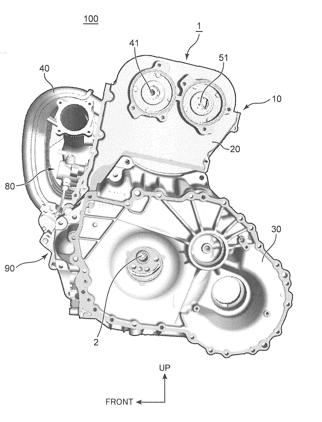
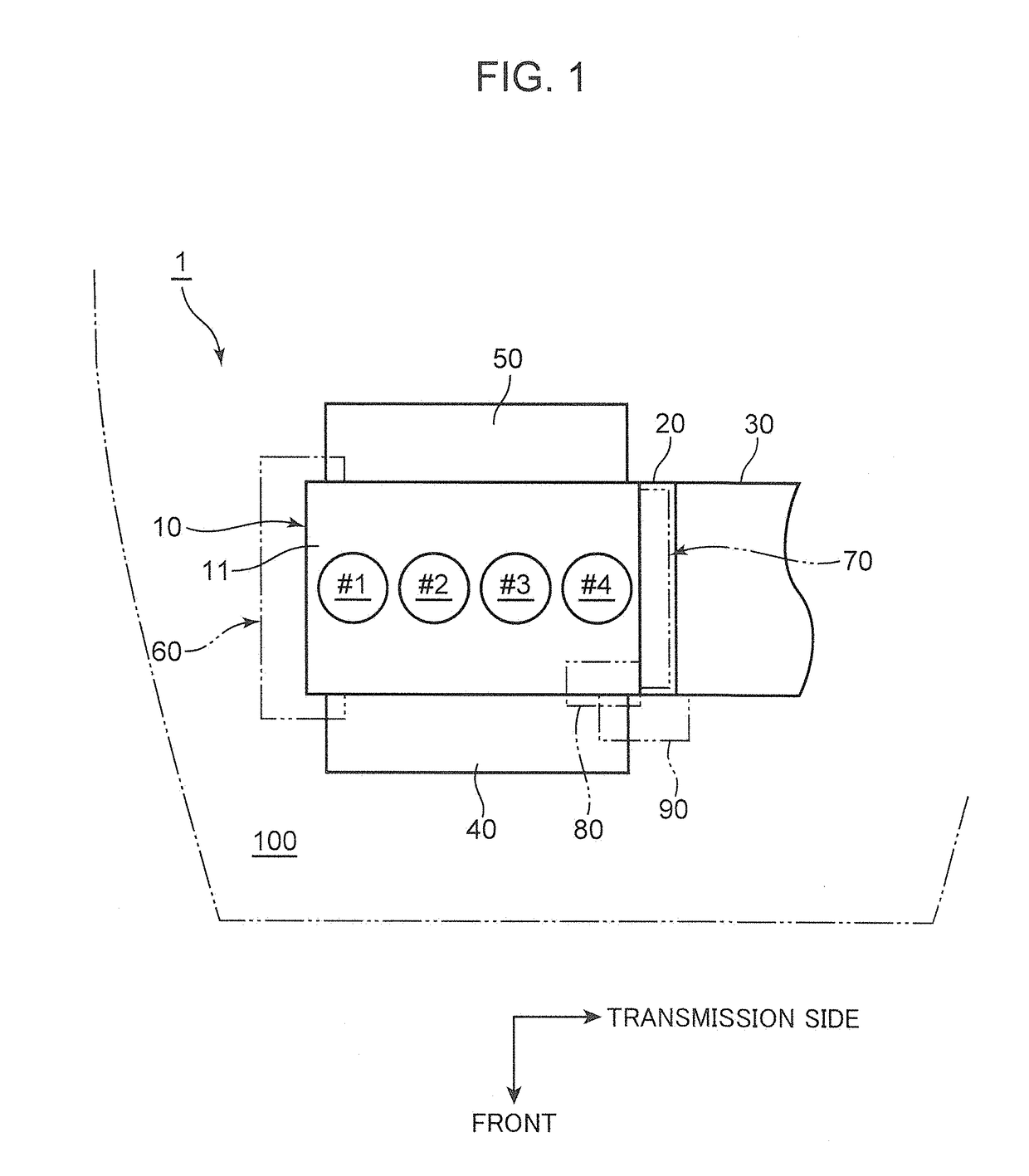
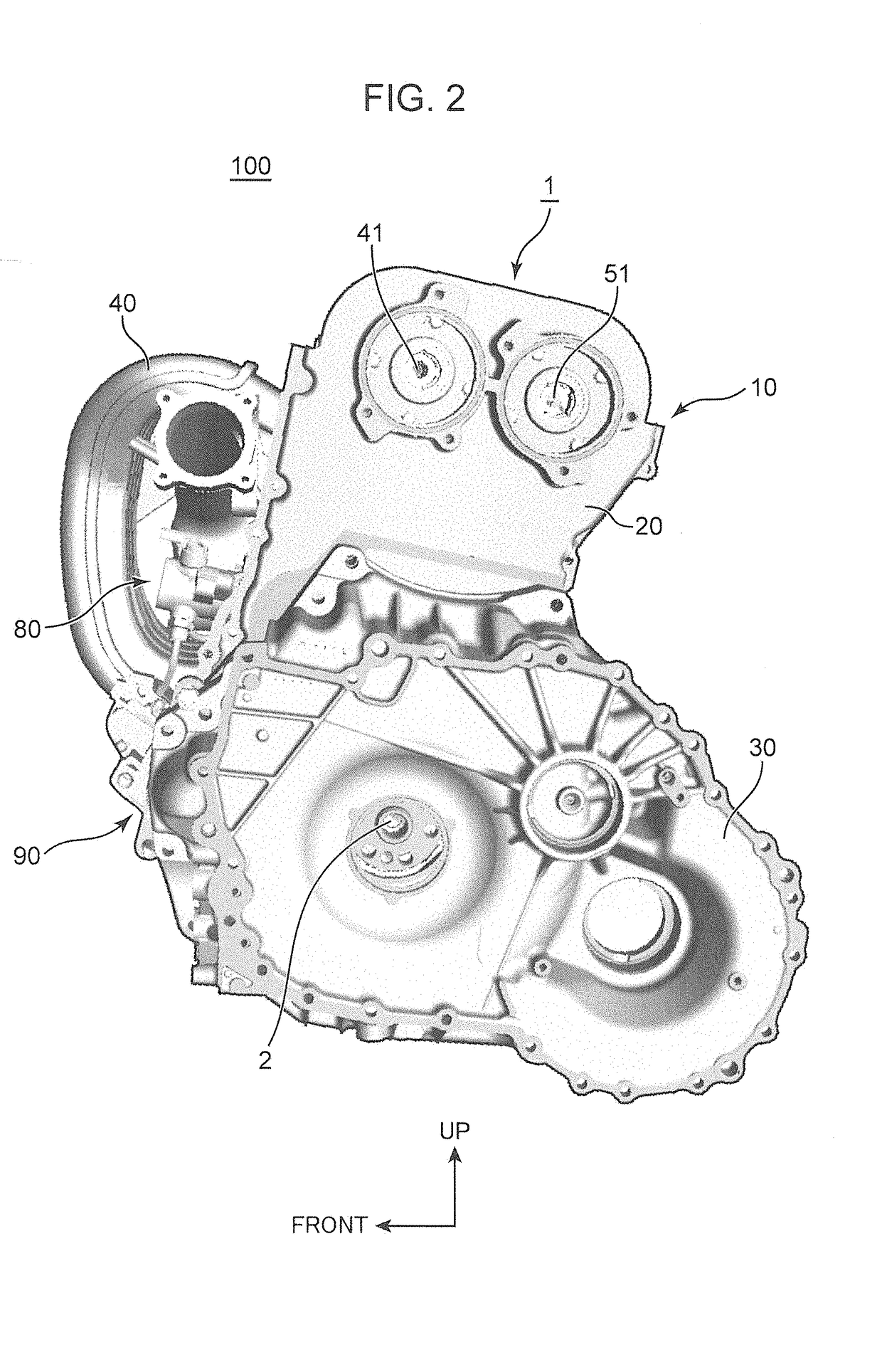
[0022]As illustrated in FIG. 1 and FIG. 2, an engine 1 according to the embodiment is an in-line 4-cylinder diesel engine (provided with a first cylinder #1, a second cylinder #2, a third cylinder #3, and a fourth cylinder #4), which is transversely mounted in an engine room 100 of a vehicle front portion in such a manner that the cylinder array direction is aligned with the vehicle width direction (an FF-vehicle). Although not illustrated, the engine 1 has a well-known structure, in which pistons, injectors (fuel injection valves), intake ports, exhaust ports, intake valves, and exhaust valves are provided on the outside or the inside of the cylinders.

[0023]As illustrated in FIG. 1, the engine 1 includes an engine body 10, in which the first to fourth cylinders #1 to #4 are arranged in a row. As illustrated in FIG. 3 and FIG. 4, the engine body 10 includes a head cover 11, a cylinder h...


PUM


Abstract

An accessory mounting structure for an engine includes an engine body, and a transmission disposed on an end of the engine body in the cylinder array direction and to which output of the engine is transmitted via a crankshaft of the engine body. When the output side of the crankshaft with respect to the transmission in the cylinder array direction is defined as a rear side, and the side of the crankshaft opposite to the rear side is defined as a front side, a fuel pump configured to feed fuel to an injector, and a starter configured to rotate the crankshaft at an engine start time are disposed on a rear end portion of an intake manifold mounting surface of the engine body. When the engine is viewed from the cylinder array direction, the starter projects outwardly with respect to the fuel pump in the engine width direction.

Description

TECHNICAL FIELD[0001]The present invention relates to an accessory mounting structure for an engine in an automobile or a like vehicle. More specifically, the present invention relates to an accessory mounting structure for an engine provided with a fuel pump configured to feed fuel to an injector.BACKGROUND ART[0002]In an automobile or a like vehicle, there is a transversely mounted engine, which is mounted in an engine room of a vehicle front portion in such a manner that the cylinder array direction is aligned with the vehicle width direction. The engine is mounted in an engine room in such a manner that a surface of an engine body on the intake side including a cylinder block faces the vehicle front side, and a surface of the engine body on the exhaust side faces the vehicle rear side. According to this configuration, it is possible to avoid lowering of an exhaust temperature due to traveling air, and to activate an exhaust purification device in an early stage and to maintain a...

Claims


Application Information

Patent Timeline
IPC IPC(8): F02B67/06F02M55/02F02F7/00
CPCF02B67/06F02F7/0007F02M55/02F02M37/043F02F7/00
Inventor EBESU, HIDESAKUNISHIDA, RYOTARO
Owner MAZDA MOTOR CORP
Why Eureka
Try Eureka