Buffer brake structure of slender object mark printing machine and complete printing control method

A buffer braking and marking machine technology, applied in printing, printing machines, rotary printing machines, etc., can solve the problems of uncontrollable number of times of characters, easy damage of the brake arm 11, delay in production, etc., and meet the speed requirements , Ensure braking accuracy and reduce personnel costs

Active Publication Date: 2016-05-04
TIANJIN JUNCHENG JINLI PIPE IND CO LTD
View PDF6 Cites 0 Cited by
  • Summary
  • Abstract
  • Description
  • Claims
  • Application Information

AI Technical Summary

Problems solved by technology

However, the above-mentioned marking machine cannot control the number of passes that can repeatedly print the required characters on the slender shape items, and at the same time achieve precise and repetitive printing with precise braking, and withstand the test of durability
[0005] CN201169121Y of Tianjin Youcheng Steel Pipe Co., Ltd. discloses a typewriter for galvanized steel pipes, which also adopts a three-wheel printing method, and its brake system uses an oil cylinder to drive a brake arm 11 hinged on the shaft. Under the use of a marking workload of about 260 tons, due to the frequent vibration of the brake wheel 14 and the impact of lifting, the brake arm 11 is easily damaged, and needs to be shut down for maintenance, delaying production

Method used


Image

  • Buffer brake structure of slender object mark printing machine and complete printing control method
  • Buffer brake structure of slender object mark printing machine and complete printing control method
  • Buffer brake structure of slender object mark printing machine and complete printing control method

Examples


Embodiment Construction

[0039] Embodiments of the present invention will be described in detail below in conjunction with the accompanying drawings, but they are not used to limit the scope of the present invention.

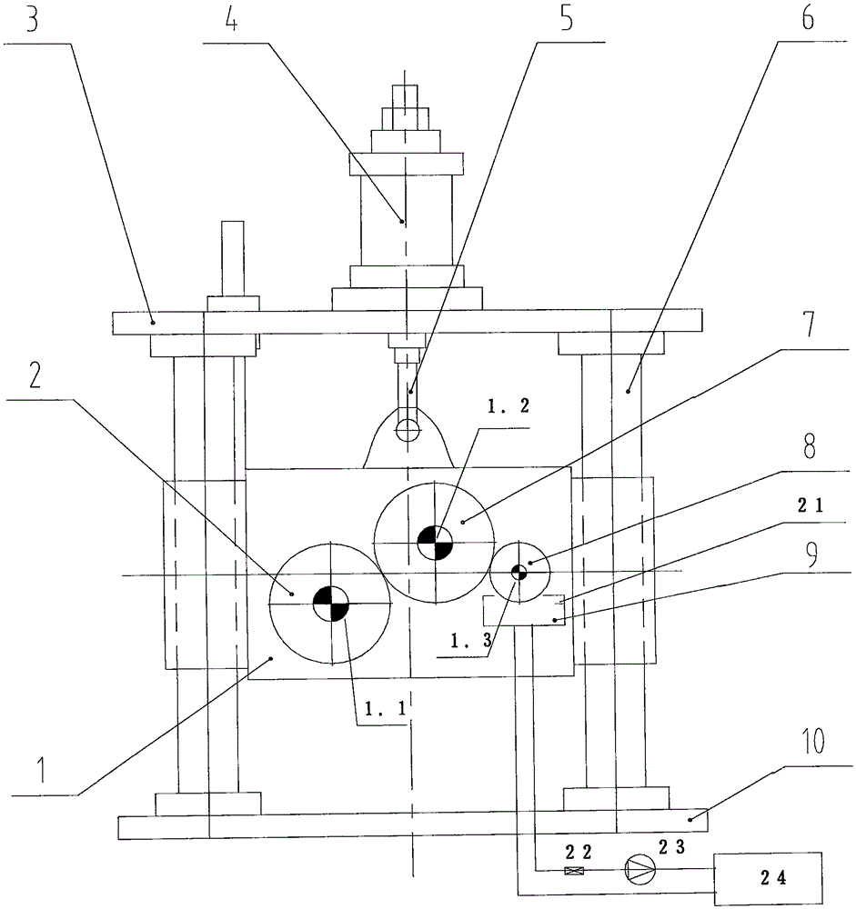
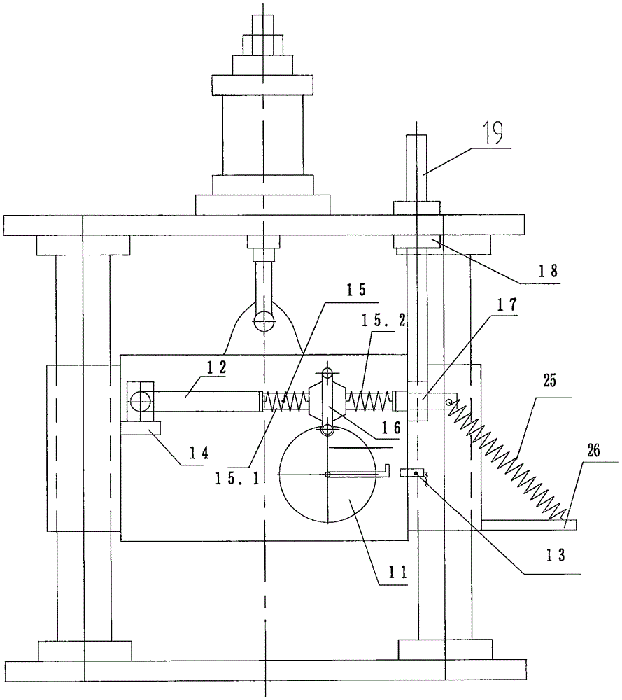
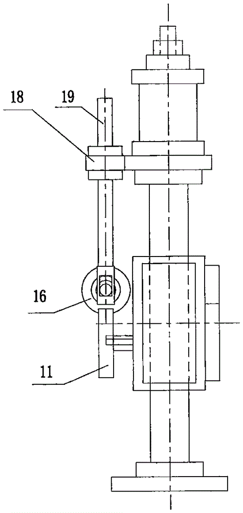
[0040] As shown in the figure, a marking machine for elongated articles includes a marking machine box 1, an upper frame plate 3, a lifting cylinder 4, a lifting arm 5, a guide rod 6 and a lower frame plate 10, and two guide rods 6 is symmetrically arranged between the upper frame plate 3 and the lower frame plate 10 to form a fixed frame, the lifting cylinder 4 is fixed on the upper frame plate 3, one end of the lifting arm 5 is connected with the piston of the lifting cylinder 4, and the lifting arm 5 is connected with the marking machine casing 1 through lugs and pin shafts, and the marking machine casing 1 has guide holes, and the guide holes are guided in the guide rods 6 .

[0041] The marking machine casing 1 has a first side and a second side; the first axis 1.1, the second axis...


PUM

PropertyMeasurementUnit
Tensile modulus of elasticityaaaaaaaaaa

Abstract

The invention discloses a buffer brake structure of a slender object mark printing machine. The buffer brake structure comprises a frame and a box; a rubber wheel (2), a character strip clamping wheel (7) and an oil pigment adhesion wheel (8), in friction fit, are arranged on one side of the box; a mark printing machine box (1) is additionally provided with a brake buffer mechanism; the brake buffer mechanism brakes a brake wheel (11) to position next printing of the rubber wheel (2) when the mark printing machine box (1) is ascended; the brake buffer mechanism includes a mounting base (14), a brake arm (12) and a buffer brake wedge; the mounting base (14) is fixed on a second side of the mark printing machine box (1); one end of the brake arm (12) is horizontally and fixedly connected to the mounting base (14) through a pin shaft; and the other end of the brake arm (12) is connected with the buffer brake wedge. The buffer brake structure of the slender object mark printing machine can control the repeated printing number on a slender object, realizes precise brake, and can stand the durability test.

Description

technical field [0001] The invention relates to the technical field of marking machines, in particular to a buffering and braking structure of a marking machine for steel pipes. Background technique [0002] According to production requirements, the surface of the steel pipe should be printed with information such as the manufacturer, production team, and steel pipe specifications. The traditional production method is to complete this process manually. This operation requires not only one operator, but also this worker has to be responsible for about 260 tons per day. Manual marking of steel pipes is labor-intensive on the one hand, and on the other hand, the quality of the marks is not high and the positions are not uniform. [0003] Through demand analysis, a marking machine is needed, which needs to print the entire group of characters completely and clearly, and can control the number of repeated printing. For example: multiple steel pipes are running on the roller line...

Claims


Application Information

Patent Timeline
IPC IPC(8): B41F13/008B41F17/10
CPCB41F13/008B41F17/10
Inventor 王亚平梅宇田建平鲍从贵汪硕
Owner TIANJIN JUNCHENG JINLI PIPE IND CO LTD
Why Eureka
Try Eureka