
Shifting device and method for operating an automatic multi-speed transmission of a motor vehicle

A technology of multi-speed transmission and shifting device, which is applied in transmission control, mechanical equipment, components with teeth, etc., can solve the problems of intensive cost and complicated layout, achieve simple structure and improve the effect of braking effect.

Active Publication Date: 2018-08-31
VOLKSWAGEN AG
View PDF6 Cites 0 Cited by
  • Summary
  • Abstract
  • Description
  • Claims
  • Application Information

AI Technical Summary

Problems solved by technology

Such an arrangement is very complex and cost-intensive, with some positions of the gear lever being used only rarely or not at all by the vehicle user

Method used


Image

  • Shifting device and method for operating an automatic multi-speed transmission of a motor vehicle

Examples


Embodiment Construction

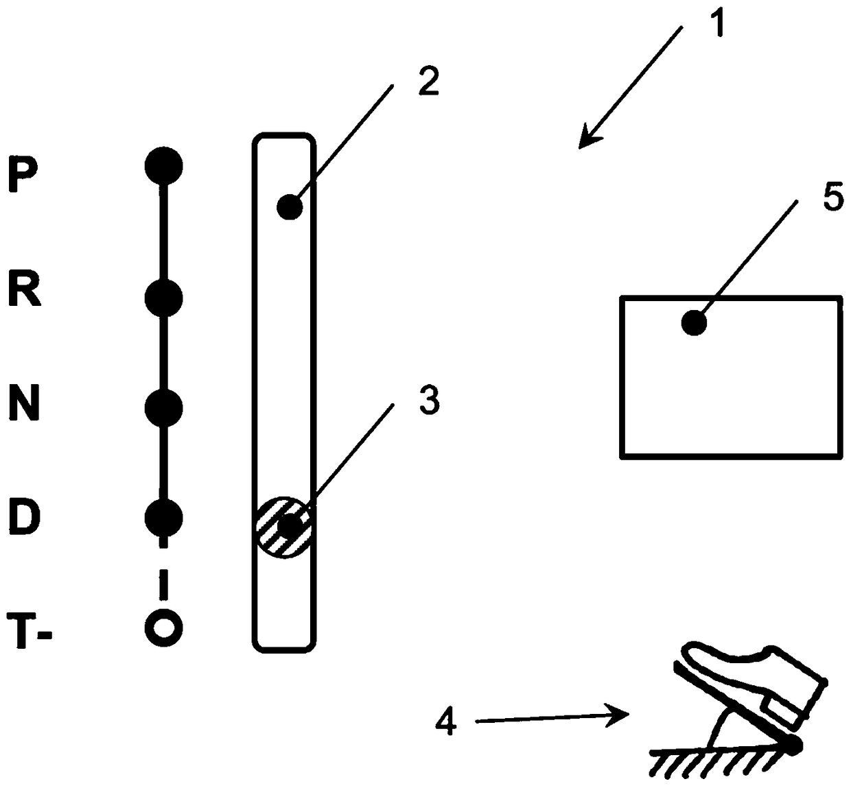
[0016] figure 1 shows a shifting device 1 with a selector gate 2 , wherein the selector gate has different positions for the selector lever 3 . From the stable parking position P, a stable reverse position R can be reached, from which then a stable parking position N can be reached, wherein a park gear is engaged in the transmission. From this parking position N, the selector lever 3 can be pivoted further into a stable forward position D. All these four positions P, R, N, D are designed as stable or detented positions, that is to say, after the shift lever 3 is deflected by the driver into one of these positions and he releases it subsequently After the selector lever, the selector lever 3 remains in this selected position. In addition, the shift gate also has an unstable position T- for downshifting, which can be reached from the forward position D. All mentioned positions P, R, N, D, T- lie on a line and the selector gate 2 is designed rectilinear. The unstable position...


PUM


Abstract

A shifting device (1) and method for operating an automatic multi-speed transmission of a motor vehicle, the shifting device having a gearshift lever (3) by means of which in a shift fork shaft shift groove (2) The deflection can select various types of driving operation, wherein the gear lever (3) has at least one first stable position (D), in which the forward gear in the transmission is automatically shifted by the controller (5), which Characteristically, the selector lever (3) has an unstable position (T-) for manual downshifts that can be reached from a first stable position (D), wherein after the driver releases the selector lever (3), the selector lever ( 3) Automatic return from the unstable position (T-) into the first stable position (D). The driver can manually select the desired lower gear in order to match the braking effect of the engine, especially when driving downhill.

Description

technical field [0001] The invention relates to a shifting device and method for operating an automatic multi-speed transmission of a motor vehicle. Background technique [0002] From EP 0 798 493 B1 a shifting device is known with a selector lever which can be pivoted in two parallel shift gates. In the first shift fork pocket, the shifter can be used in stable park position (P), reverse position (R), park position (N), forward with unlimited automatic gear selection position and three additional stable positions ("3, 2, 1"). In the three positions of the selector lever ("3, 2, 1"), the gear is still automatically selected by the controller, but this determines the highest engageable gear according to the position of the selector lever and only in the lower selected under the gear. In the second shift fork pocket, the driver can move the shift lever forward (upshift) or backward (downshift) from a stable position to one of two unstable positions (+, -) Medium deflection...

Claims


Application Information

Patent Timeline
Patent Type & Authority Patents(China)
IPC IPC(8): F16H59/10
Inventor H.迪特里希S.巴甘兹
Owner VOLKSWAGEN AG
Learn More