Multi-loop control device in vehicle braking system

A technology of vehicle braking and control device, applied in the direction of brake transmission, hydraulic brake transmission, brake, etc., can solve the problems of the brake wheel cylinder not working, the loss of brake fluid, the failure of the brake system, etc. Improved shutdown effect, guaranteed braking performance, improved safety performance

Active Publication Date: 2017-09-05
SHANDONG JIAOTONG UNIV
View PDF5 Cites 0 Cited by
  • Summary
  • Abstract
  • Description
  • Claims
  • Application Information

AI Technical Summary

Problems solved by technology

However, during the running of the vehicle, under complex road conditions, the leakage of the brake pipeline often occurs due to the impact of foreign objects and other reasons. The brake fluid leaks out, causing the brake wheel cylinder connected to the pipeline to fail to work, and due to the continuous leakage of the pipeline, the brake fluid gradually loses, which will further cause the rest of the brake wheel cylinders to also fail to work normally, resulting in vehicle failure. Brake system failure, causing serious safety hazards

Method used


Image

  • Multi-loop control device in vehicle braking system
  • Multi-loop control device in vehicle braking system
  • Multi-loop control device in vehicle braking system

Examples


Embodiment 1

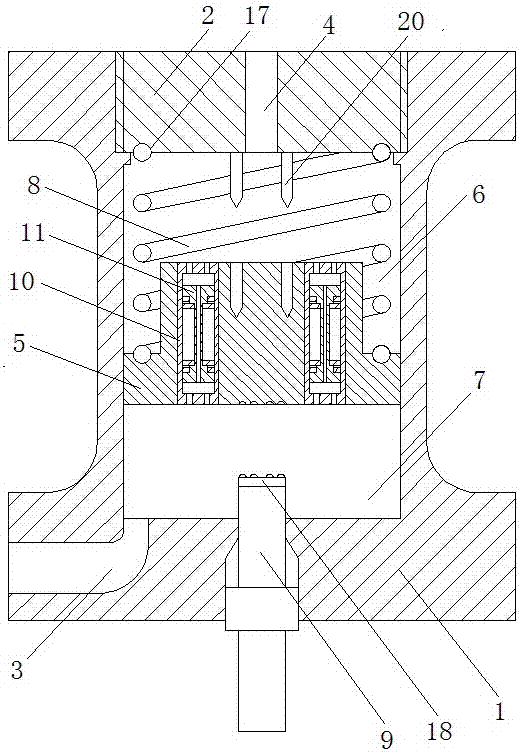
[0029] Such as figure 1 A multi-circuit control device in a vehicle braking system is shown, which includes a control cylinder 1, the upper end of the control cylinder 1 is provided with an end cover 2, and the inside of the control cylinder 1 is provided with a cavity. 1 is provided with an oil inlet 3 and an oil outlet 4 extending to the inside of the cavity, and the end cover 2 and the control cylinder 1 are connected by threads. A piston 5 is arranged in the cavity, and its side end surface is attached to the inner wall of the cavity. In the cavity, the cavity area between the piston 5 and the upper end surface of the cavity is the upper cavity 6, and the piston 5 and the cavity The cavity area between the lower end surfaces is the lower cavity 7, the oil inlet 3 is connected to the lower cavity 7, the oil outlet 4 is arranged in the end cover 2, and it is connected to the inside of the upper cavity 6; The end of the oil outlet 4 in the upper cavity 6 is located at the ax...

Embodiment 2

[0039] As an improvement of the present invention, in each diversion valve, the diameter of the first diversion hole is 3 millimeters, and the diameter of the second diversion hole is 0.8 millimeters, which can pass through the first diversion hole and the second diversion hole. The micro-diameter of the hole is set to form a good throttling effect on the brake fluid.

[0040] The remaining features and advantages of this embodiment are the same as those of Embodiment 1.

Embodiment 3

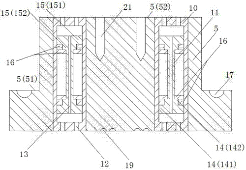
[0042] As an improvement of the present invention, such as Figure 4 As shown, in each diversion valve, the axis of the second diversion hole 13 inside the diversion valve core 11 extends in a corrugated shape in the vertical direction. With the above design, when the brake fluid flows inside, the corrugated structure of the second diversion hole can extend the flow path of the brake fluid, so that the second diversion hole can save the brake fluid. The flow effect is more significant, so that the hydraulic pressure of the brake fluid in the lower cavity can be guaranteed relative to the upper cavity, so as to improve the working performance of the control device in this application.

[0043] The remaining features and advantages of this embodiment are the same as those of Embodiment 2.


PUM


Abstract

The invention discloses a multi-loop control device in a vehicle braking system, which includes a control cylinder, an end cover is arranged on the upper end of the control cylinder, a cavity is arranged inside the control cylinder, and a There is an oil inlet and an oil outlet extending to the inside of the cavity; a piston is arranged in the cavity, and an adjustment spring is connected to the upper end of the piston. In the cavity, the lower end of the piston and the upper end of the piston are connected to each other; the above technical solution is adopted The multi-loop control device in the vehicle braking system can control each braking circuit when the vehicle braking system contains multiple braking circuits. When any brake circuit leaks, the control device corresponding to the brake circuit can automatically cut off the brake circuit to ensure that the rest of the brake circuits maintain normal working conditions while avoiding brake fluid leakage. Therefore, the braking performance of the vehicle can be guaranteed, thereby significantly improving the safety performance of the vehicle in a fault state.

Description

technical field [0001] The invention relates to an auxiliary control component in a vehicle braking system, in particular to a multi-loop control device in the vehicle braking system. Background technique [0002] The braking system of a vehicle is one of the working systems directly related to the driving safety of the vehicle, and the reliability of the braking system is crucial to the safety of the vehicle. In existing vehicle braking systems, a single braking circuit is often used, that is, the brake master cylinder is directly connected to the brake wheel cylinder. However, during the running of the vehicle, under complex road conditions, the leakage of the brake pipeline often occurs due to the impact of foreign objects and other reasons. The brake fluid leaks out, causing the brake wheel cylinder connected to the pipeline to fail to work, and due to the continuous leakage of the pipeline, the brake fluid gradually loses, which will further cause the rest of the brake...

Claims


Application Information

Patent Timeline
Patent Type & Authority Patents(China)
IPC IPC(8): B60T11/32
CPCB60T11/323
Inventor 吴娜
Owner SHANDONG JIAOTONG UNIV
Why Eureka
Try Eureka