Eureka AIR delivers breakthrough ideas for toughest innovation challenges, trusted by R&D personnel around the world.

O-Ring Plunger for a Prefilled Syringe and Method

Inactive Publication Date: 2018-02-15
BECTON DICKINSON & CO
View PDF3 Cites 17 Cited by
  • Summary
  • Abstract
  • Description
  • Claims
  • Application Information

AI Technical Summary

Benefits of technology

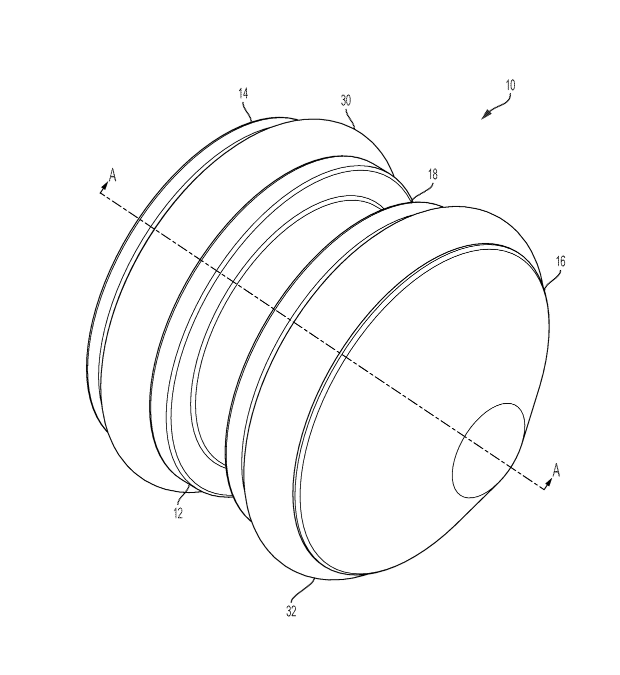
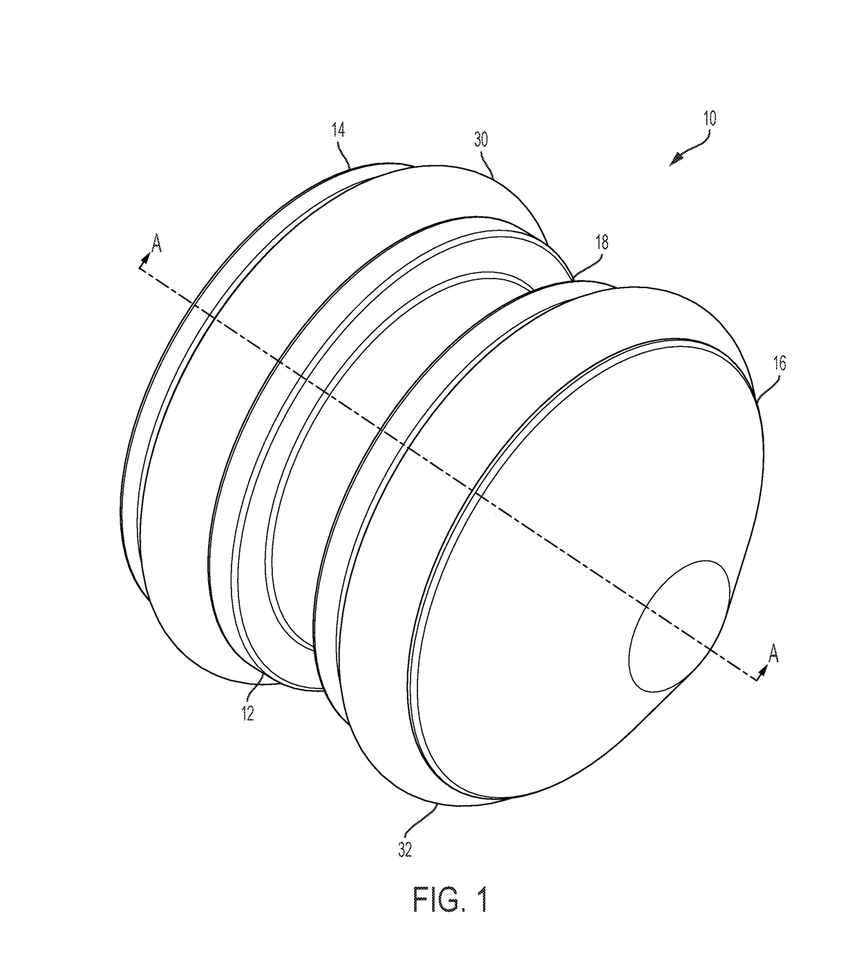
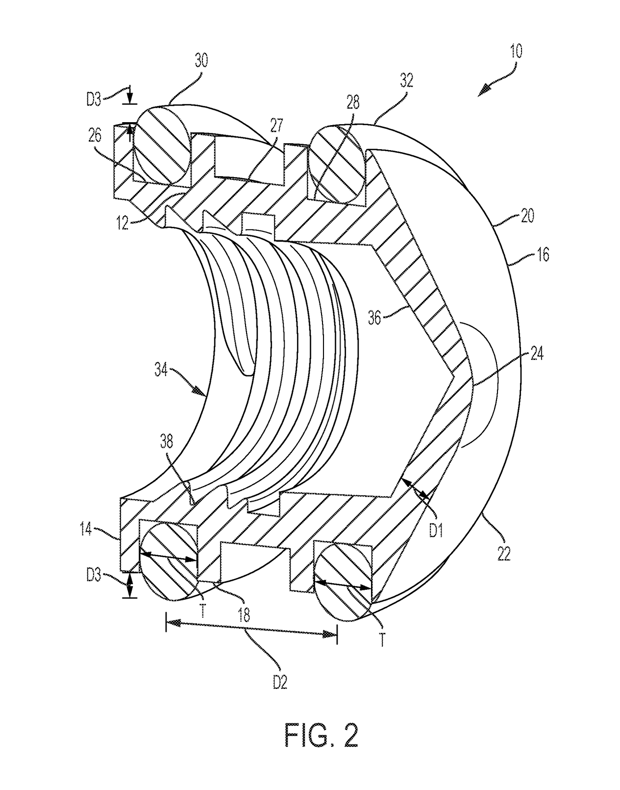
The patent describes a plunger for a syringe that can be slidably advanced to expel fluid. The plunger includes a head portion with a proximal end, a distal end, and an annular sidewall extending therebetween. The plunger also includes at least two annular grooves that are spaced apart in a longitudinal direction by a gap. The plunger further includes annular seals that protrude radially beyond the sidewall to form a slideable seal with the inner sidewall of the syringe barrel. The plunger can be lubricated with silicone and can be made from different materials like polypropylene, polyethylene, cyclic olefin polymer or copolymer, polycarbonate, and polyester. The plunger can be easily inserted into the syringe barrel to form a prefilled syringe. The technical effects of this patent include improved sealing with the syringe barrel, reduced friction during sliding, and improved lubrication of the plunger.

Problems solved by technology

Since only the protrusions or ribs of the plunger sidewall actually contact the syringe barrel, a large portion of the surface area of the coated or lubricated plunger or stopper does not actually contribute to the sliding properties of the syringe and stopper.
Such a process can significantly increase the cost of manufacturing the syringe.
Furthermore, significant waste materials are also produced during the compression molding process.

Method used


Image

  • O-Ring Plunger for a Prefilled Syringe and Method
  • O-Ring Plunger for a Prefilled Syringe and Method
  • O-Ring Plunger for a Prefilled Syringe and Method

Examples


Embodiment Construction

[0039]For purposes of the description hereinafter, the terms “upper”, “lower”, “right”, “left”, “vertical”, “horizontal”, “top”, “bottom”, “lateral”, “longitudinal”, and derivatives thereof shall relate to the invention as it is oriented in the drawing figures. The term “proximal” is used to refer to a portion of a device or object that is closest to or manipulated by a user. The term “distal” refers to the portion of the device or object farthest away from the portion manipulated by a user. For example, the end of a syringe grasped by a user is the proximal end, and fluid is expelled from the distal end of the syringe. However, it is to be understood that the invention may assume various alternative variations except where expressly specified to the contrary. It is also to be understood that the specific devices illustrated in the attached drawings, and described in the following specification, are simply exemplary embodiments of the invention. Hence, specific dimensions and other ...


PUM


Abstract

A multi-piece plunger configured to be slideably advanced through a syringe barrel to expel fluid therefrom is provided. The plunger includes a head portion having a proximal end, a distal end, and an annular sidewall extending therebetween. The sidewall can define at least two annular grooves. The plunger also includes annular seals disposed within each of the at least two annular grooves, such that at least a portion of each of the annular seals protrudes radially beyond an outer surface of the sidewall to form a slideable seal with an inner sidewall of the syringe barrel. The head portion can be formed from a first material, such as a rigid plastic material, and the annular seals can be formed from a second material, such as a thermoset rubber or a thermoplastic elastomer. A prefilled syringe including the multi-piece plunger is also provided herein.

Description

BACKGROUND OF THE INVENTIONField of the Invention[0001]The invention relates, in general, to a plunger for use with a syringe, such as a prefilled syringe containing a therapeutic agent to be injected to a patient, and, more particularly, to a multi-piece plunger including a head portion and one or more elastomeric annular seals.Description of Related Art[0002]Current syringe designs generally include a tubular barrel having an access opening formed at one end, and a smaller discharge opening (e.g., a nozzle) formed at the opposing end. A lead end of an elongated plunger is received within the access opening of the barrel so as to be slidable within the barrel. Attached to or integral with the lead end of the plunger is a flexible sealing member or stopper that snugly seals against the interior surface of the barrel. A needle, a threaded member, or a non-threaded member is usually attached to the discharge opening on the barrel. The needle can be used to penetrate a surface while th...

Claims


Application Information

Patent Timeline
IPC IPC(8): A61M5/315
CPCA61M5/31515A61M2207/00A61M5/31513A61M5/178A61M2205/0222
Inventor COJOCARIU, GHEORGHERYAN, KEVIN M.
Owner BECTON DICKINSON & CO
Why Eureka
Eureka Blog
Learn More