Wireless control system for floating row cleaner

a row cleaner and wireless control technology, applied in the field of row cleaners, can solve the problems of reducing the physical space available for mounting a row cleaner, affecting the yield of the row cleaner, so as to reduce the cost of chemical cleaning, reduce erosion, and increase yield

Active Publication Date: 2018-03-01
MARTIN RONALD S
View PDF5 Cites 5 Cited by
  • Summary
  • Abstract
  • Description
  • Claims
  • Application Information

AI Technical Summary

Benefits of technology

[0005]A large of number of corn acres are planted with a row spacing of 30-38 inches. For various reasons, including increased yields, decreasing erosion and decreasing chemical costs, farmers are interested in reducing row spacing to less than 30 inches. Reductions to a row spacing of 15-20 inches is therefore desirable. The reduction in width between planted rows in combination with the use of row cleaners can lead to plugging of the planter row units i.e. the volume of trash flow is too high for the amount of actual physical space available between planter row units contiguously mounted on a tool bar. Furthermore, the reduced spacing between row units reduces the physical space available for mounting a row cleaner to a row unit. This problem is especially an issue for planters having a split row type, such as the 1700 Series John Deere front-fold planter. Applicant's design is of benefit and desirable. Additionally, many users wish to mount an accessory tool with the row cleaner, i.e. a coulter mounted in combination with a row cleaner for each row unit.

Problems solved by technology

The reduction in width between planted rows in combination with the use of row cleaners can lead to plugging of the planter row units i.e. the volume of trash flow is too high for the amount of actual physical space available between planter row units contiguously mounted on a tool bar.
Furthermore, the reduced spacing between row units reduces the physical space available for mounting a row cleaner to a row unit.
This problem is especially an issue for planters having a split row type, such as the 1700 Series John Deere front-fold planter.

Method used


Image

  • Wireless control system for floating row cleaner
  • Wireless control system for floating row cleaner
  • Wireless control system for floating row cleaner

Examples


Embodiment Construction

[0027]The present invention will now be described in more detail with reference to exemplary embodiments as shown in the accompanying drawings. While the present invention is described herein with reference to the exemplary embodiments, it should be understood that the present invention is not limited to such exemplary embodiments. Those possessing ordinary skill in the art and having access to the teachings herein will recognize additional implementations, modifications, and embodiments, as well as other applications for use of the invention, which are fully contemplated herein as within the scope of the present invention as disclosed and claimed herein, and with respect to which the present invention could be of significant utility.

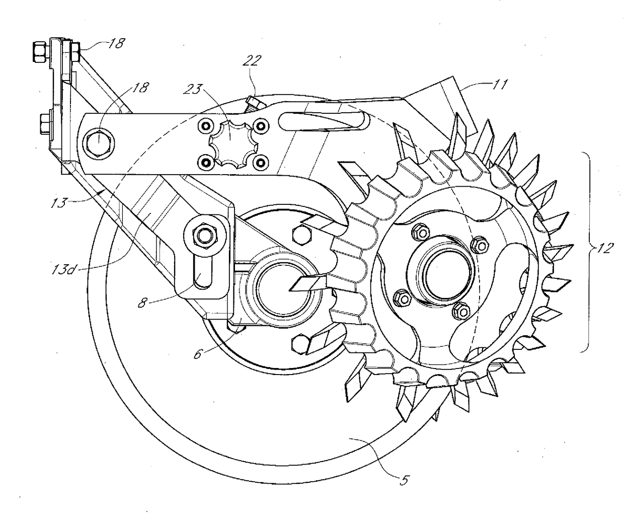
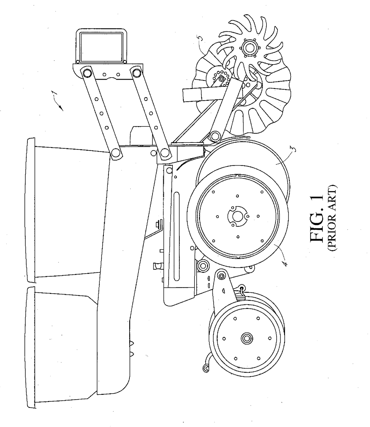
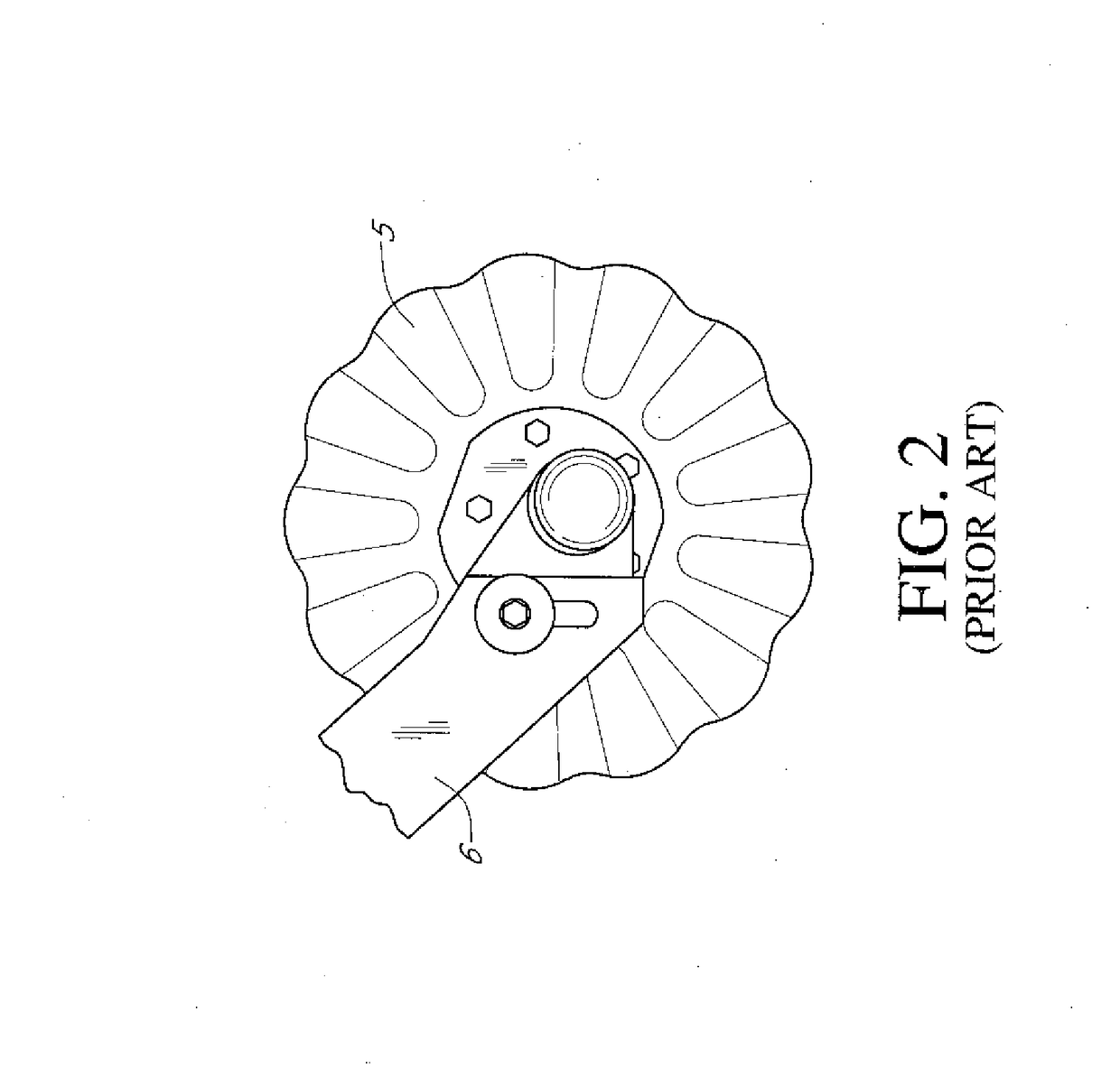
LISTING OF ELEMENTSElement DescriptionElement NumberPlanter row unit  1Front plate  2Row unit disc opener  3Planter depth tire  4Coulter  5Tool arm  6Tool arm first end  6aTool arm second end  6bHub  7Slotted aperture  8Row cleaner assembly 10Row cleane...


PUM


Abstract

A wireless control system may include a controller and portable computing device. The controller may be configured to communicate with the portable computing device so that an operator may set a specific value and / or parameters in which the hydraulic cylinder may operate. In an aspect, the hydraulic cylinder may be engaged with a row cleaner assembly, and in another aspect it may be engaged with a closing wheel, and in yet another aspect it may be engaged with a furrow forming assembly.

Description

CROSS-REFERENCE TO RELATED PATENT APPLICATIONS[0001]This patent application claims priority to U.S. Provisional Patent Application No. 62 / 380,936, filed Aug. 29, 2017, entitled “WIRELESS CONTROL SYSTEM,” which application is hereby incorporated by reference herein in the entirety.FIELD OF INVENTION[0002]The methods described herein are generally applicable to the field of agricultural equipment. The embodiments shown and described herein are more particularly for improved row cleaning for delivery of seed or fertilizer. Although in no way limiting, the present disclosure is particularly suited for minimum or no-till conditions.BACKGROUND OF THE INVENTION[0003]U.S. Pat. No. 4,785,890 issued to Martin for “Ground-driven rotary row cleaner” illustrates prior art that may be relevant to the invention disclosed and claimed herein, but which fails to teach the improvement disclosed and claimed herein.SUMMARY OF THE INVENTION[0004]Applicant discloses and claims herein a row cleaner frame a...

Claims


Application Information

Patent Timeline
Patent Type & Authority Applications(United States)
IPC IPC(8): A01B63/32G05D1/00A01C5/06A01B27/00
CPCA01B63/32G05D1/0011A01C5/064A01B27/005A01C5/068A01C7/006A01B5/04A01B15/18A01C7/205Y02P60/20
Inventor MARTIN, RONALD S.
Owner MARTIN RONALD S
Why Eureka
Try Eureka