

Outboard motor
a technology for outboard motors and transmissions, which is applied in the direction of vessel parts, vessel construction, gearing, etc., can solve the problems of undesirably increasing the size of outboard motors, complicated structure, and undesirably increasing the size of transmissions
- Summary
- Abstract
- Description
- Claims
- Application Information
AI Technical Summary
Benefits of technology
Problems solved by technology
Method used
Image

Examples
first embodiment
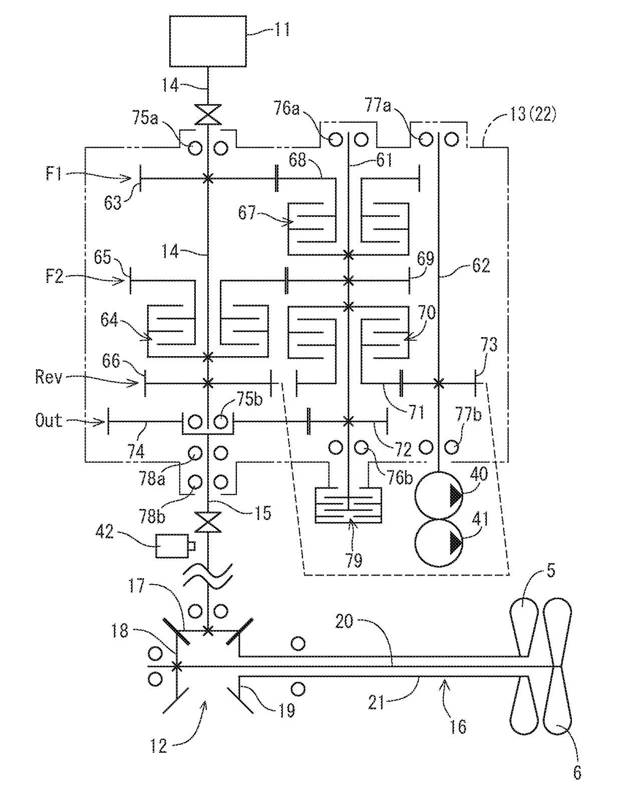
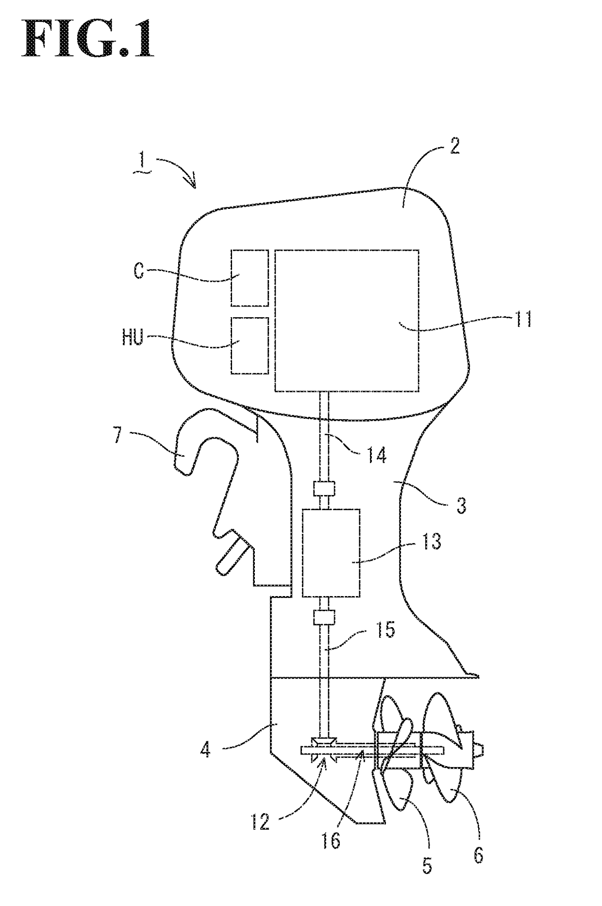
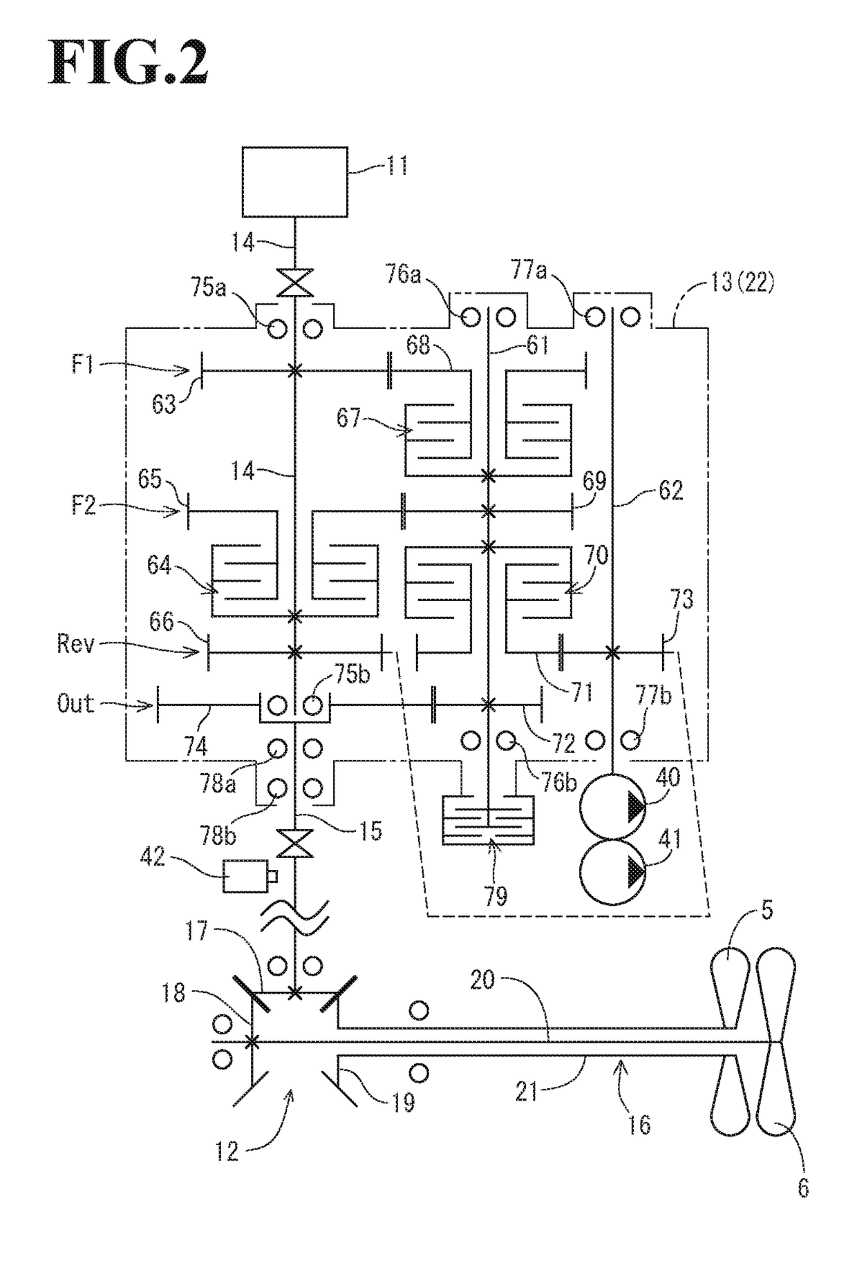
[0043]The outboard motor 1 of the first embodiment includes a driving source, which is an engine 11 in this embodiment, a lower gear mechanism 12, a transmission 13, an input shaft 14, and an output shaft 15. The lower gear mechanism 12 is located below the engine 11 and drives the front and rear propellers 5 and 6. The transmission 13 is located between the engine 11 and the lower gear mechanism 12. The input shaft 14 transmits power from the engine 11 to the transmission 13. The output shaft 15 transmits power from the transmission 13 to the lower gear mechanism 12.
[0044]The engine 11 is mounted inside the engine cover 2. The engine 11 of the first embodiment is a vertical water-cooled engine, in which the engine output shaft, that is, the crankshaft (not shown) extends in the vertical direction. The lower gear mechanism 12 is accommodated in the lower unit case 4. The lower unit case 4 rotationally supports a laterally extending propeller shaft 16 that drivingly rotates the front...
second embodiment
[0088]In the second embodiment, the rotational speed of the output shaft 15 is detected using a rotational speed detection sensor 142 (refer to FIG. 7). The connection and disconnection of the forward low-speed clutch 127, the forward high-speed and reverse clutch 130, and the forward / reverse switching clutch 137 are configured to be automatically controlled depending on the relationship between the rotational speeds of the engine 11 and the output shaft 15. The connection and disconnection of the forward low-speed clutch 127, the forward high-speed and reverse clutch 130, and the forward / reverse switching clutch 137 may be configured to be manually controlled using, for example, a lever.
[0089]In the second embodiment, the input shaft 14 and the main relay shaft 123 are configured to be constantly rotated by the rotational power when the engine 11 is driven. The lowest end portion of the main relay shaft 123 projects downward from the lower plate portion of the transmission case 122...
third embodiment
[0109]A one-way clutch 233 is located between the forward shaft 223 and the forward / reverse relay gear 232. The one-way clutch 233 transmits the forward output from the forward shaft 223 to the forward / reverse relay gear 232, but does not transmit the forward output in reverse. The one-way clutch 233 of the third embodiment is a sprag clutch.
[0110]In this case, when only the forward low-speed clutch 227 is coupled from the neutral state, and the forward shaft 223 is rotated in the forward output direction, sprags 234 between the forward shaft 223 and the forward / reverse relay gear 232 rise since the forward / reverse relay gear 232 is not driven. Thus, a great frictional force is generated between the sprags 234 and the orbital planes of the forward shaft 223 and the forward / reverse relay gear 232. Consequently, the forward / reverse relay gear 232 is rotated integrally with the forward shaft 223 (refer to FIG. 18A). As a result, the forward low-speed output is transmitted from the forw...
PUM
 Abstract
Description
Claims
Application Information