Load transferring and self-adjusting saddle system for floor jacks and jack stands apparatus and method

Inactive Publication Date: 2018-03-01
LOVELESS M JAMIN
View PDF1 Cites 1 Cited by
  • Summary
  • Abstract
  • Description
  • Claims
  • Application Information

AI Technical Summary

Benefits of technology

The invention provides a load bearing lifting surface, load bearing saddle, and support mechanism for a jacking apparatus that allows for secure locking and unlocking of the saddle while under load. The lifting surface and saddle can easily be transferred from the lifting device to a support stand while under load, and the support stand can securely hold the load. The load bearing component is not permanently attached to either the lifting device or the support stand, allowing for an essential static load to be transferred without moving it. The method involves positioning the lifting device under the load, elevating the saddle to engage the load, and connecting the saddle to the support stand. This allows for easy transfer of the load to the support stand while maintaining the saddle in a secure position.

Problems solved by technology
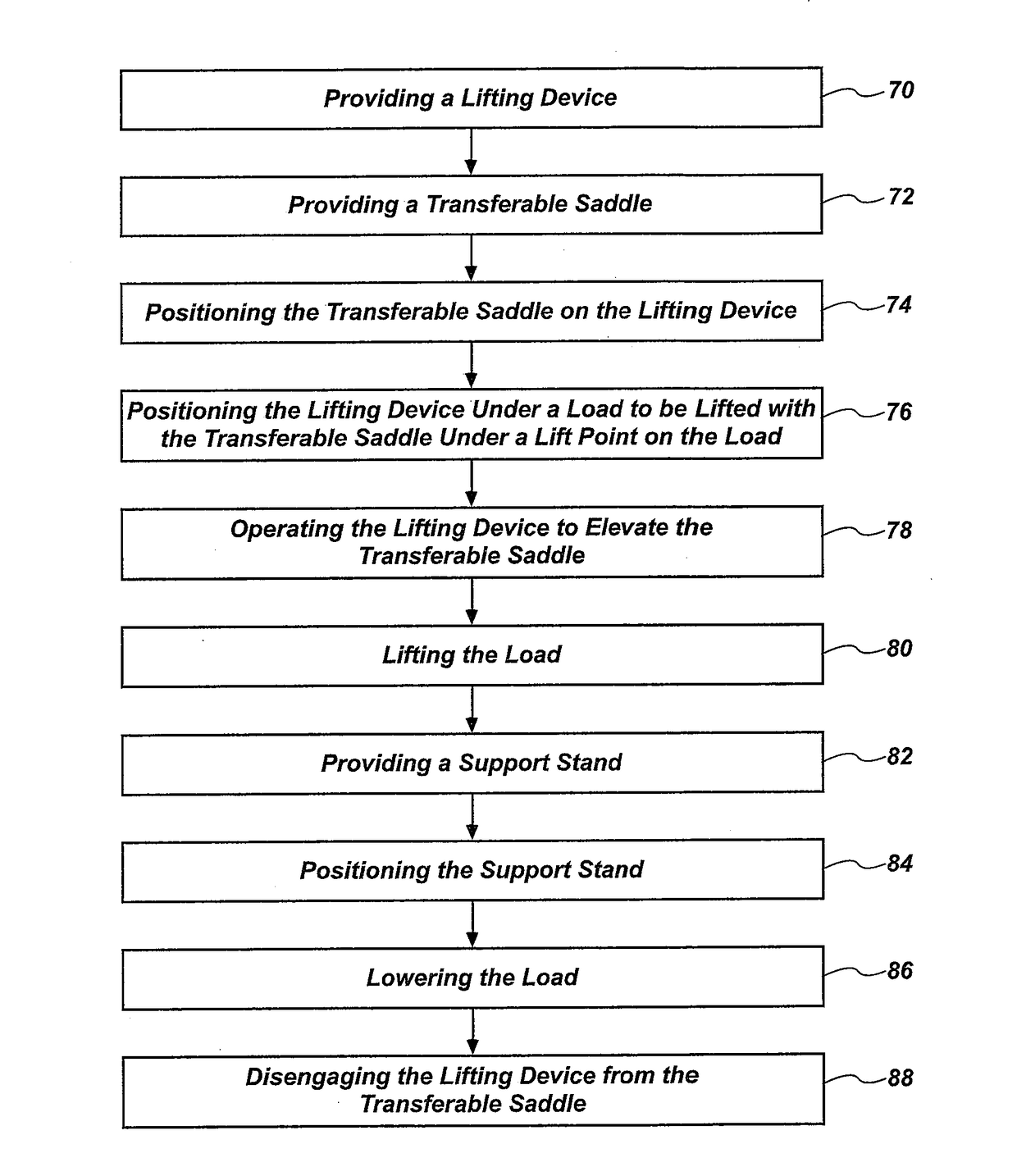
This is complicated by the fact that certain makes of cars are designed with only one safe, suitable lift point under the vehicle (e.g., all 1997 and later models of CORVETTE®) making the transfer of the vehicle from a lifting device to a suitable support structure especially difficult.
Other designs currently seeking to address this issue possess inherent limitations that decrease their usability and appeal.
Some may involve complex and / or proprietary construction techniques.
Some may add to the base height of the lifting apparatus or jack, thereby limiting their ability to get under vehicles or loads that have limited ground clearance.
This can be made even more problematic for a car that has a flat tire.
For example, having to move under a car supported only by a jack in order to find a suitable location for jack stands is inherently dangerous and can be time consuming.
Moreover, as described with certain vehicles, such a process can be extremely difficult or even impossible as the structure is intended to be held only by the dedicated, recommended lift points, which become inaccessible for a stand when being used or occupied by the jack itself.
Traditional methods of lifting a vehicle also often cause damage to the underside of the vehicle due to the shifting of the angle of the load as the vehicle is raised, causing the load to be borne at an edge or corner of the lifting surface, rather than having the weight evenly distributed over the entire lifting surface.
Additionally, once a stand is in place, lifting the other side of the vehicle will cause the stand to unbalance as the load shifts back, often necessitating the dangerous need to “tap” the first stand back into place with a hammer after the load is raised and supported on two stands.

Method used


Image

  • Load transferring and self-adjusting saddle system for floor jacks and jack stands apparatus and method
  • Load transferring and self-adjusting saddle system for floor jacks and jack stands apparatus and method
  • Load transferring and self-adjusting saddle system for floor jacks and jack stands apparatus and method

Examples


Embodiment Construction

[0045]It will be readily understood that the components of the present invention, as generally described and illustrated in the drawings herein, could be arranged and designed in a wide variety of different configurations. Thus, the following more detailed description of the embodiments of the system and method of the present invention, as represented in the drawings, is not intended to limit the scope of the invention, as claimed, but is merely representative of various embodiments of the invention. The illustrated embodiments of the invention will be best understood by reference to the drawings, wherein like parts are designated by like numerals throughout.

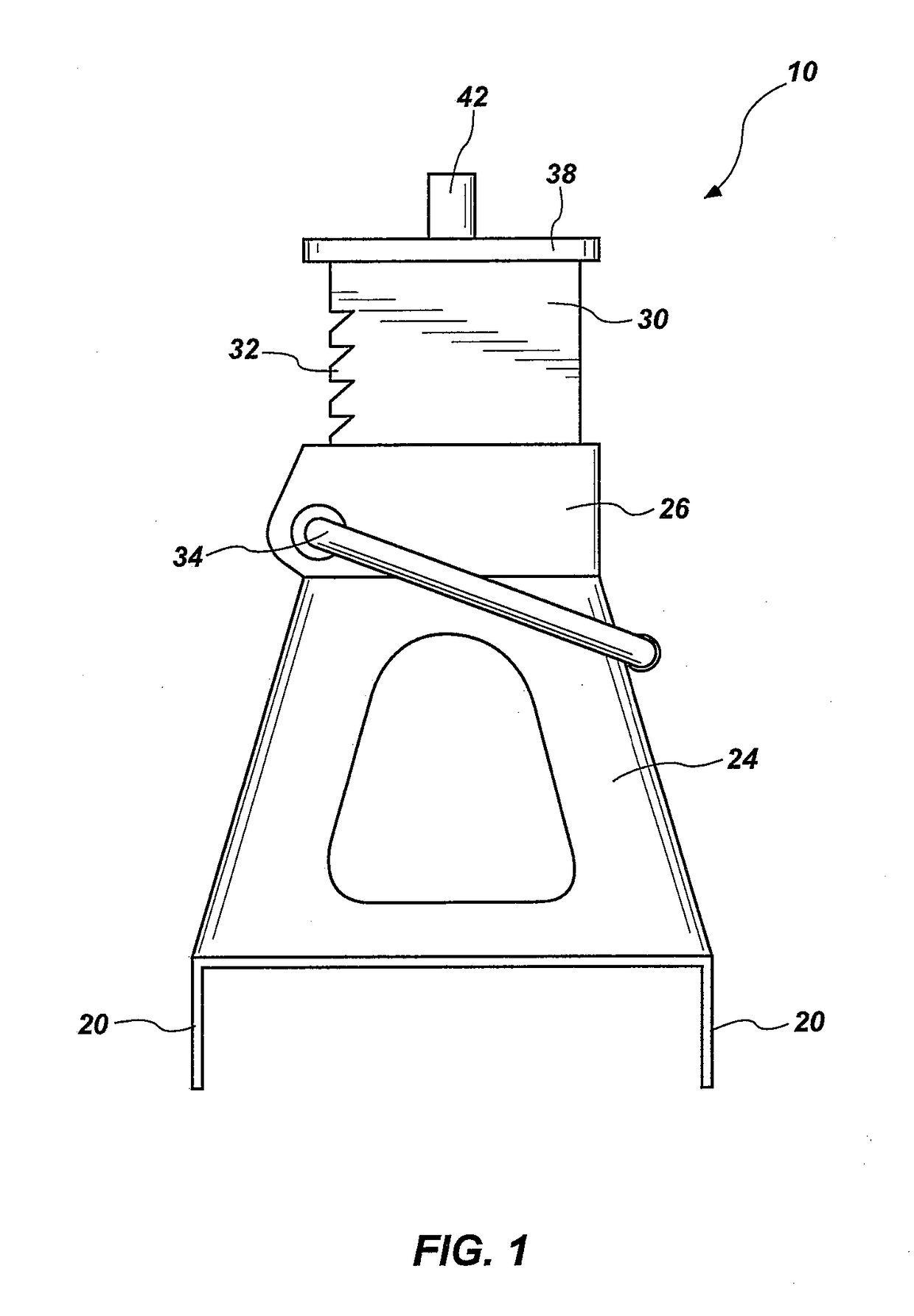
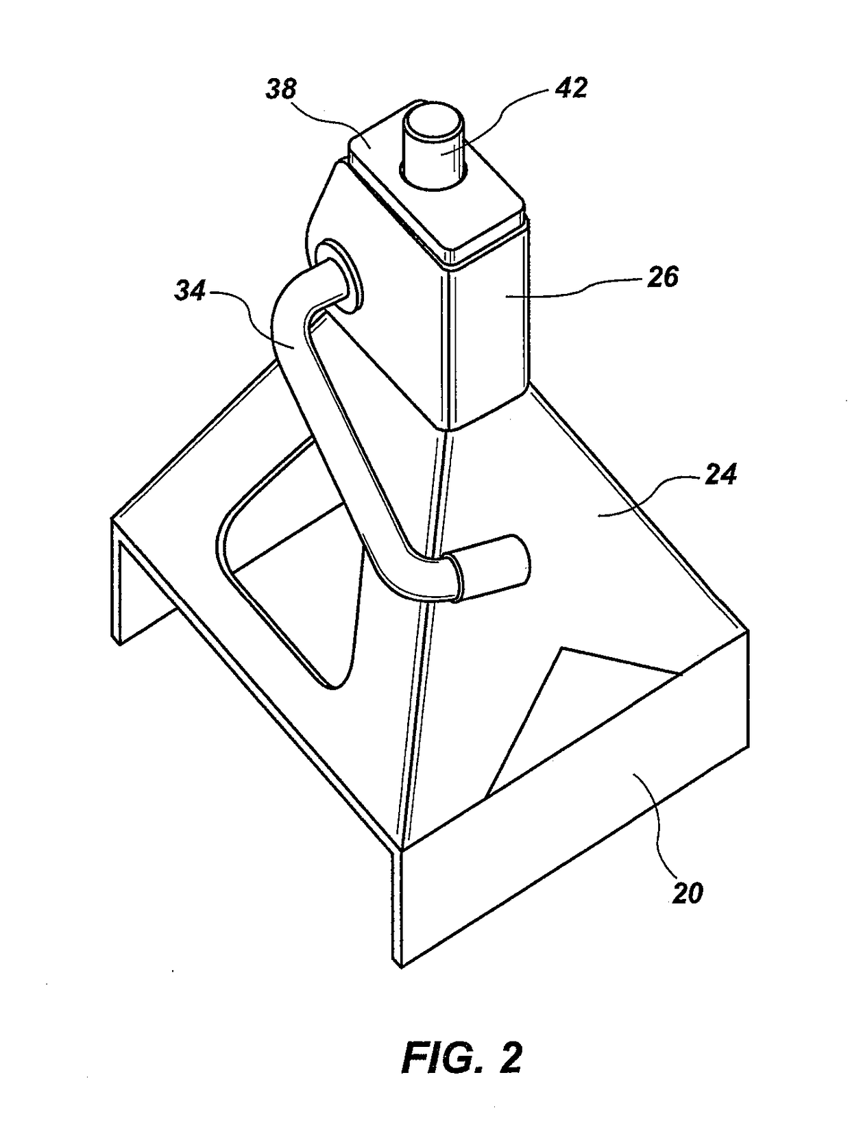
[0046]Referring to FIG. 1, a support stand 10, or support structure 10 or jack stand 10, may include various parts, or sections. The support stand 10 may include a base 20 that contacts the ground or floor. The base 20 may include two faces on opposite sides of the support stand 10 and spaced apart to form a base alley 22, or a ...


PUM


Abstract

A system for lifting a load and being able to transfer the load from a lifting device to a support structure and back to the lifting device, all while utilizing the same lift point on the load. The system includes a saddle that is removable and transferrable between the lifting device and the support structure, which does not add to the base height or mechanical complexity of the system as a whole. Thus, the saddle may engage the load and the load may be safely and conveniently transferred between the lifting device and support structure, all while the saddle remains essentially stationary.

Description

RELATED APPLICATIONS[0001]This application claims the benefit of U.S. Provisional Patent Application Ser. No. 62 / 378,862, filed on Aug. 24, 2016, which is hereby incorporated by reference in its entirety.BACKGROUND1. The Field of the Invention[0002]The invention relates to an apparatus, or system that includes multiple structures, and a method used to raise a vehicle or other load from the ground with a floor jack, be it hydraulic, screw type, or other, and then allow the load to be transferred to a jack stand or similar support structure.2. Background[0003]There are many reasons a car, or other vehicle, may need to be elevated. For example, a car may need to be elevated to facilitate changing a tire, replacing brake pads, or some other maintenance. A trailer or any other wheeled vehicle may need to be elevated for similar reasons.[0004]The traditional methods require a user to locate a suitable support location for support structures (i.e., jack stands) under the load or vehicle wh...

Claims


Application Information

Patent Timeline
IPC IPC(8): B66F5/02
CPCB66F5/02B66F13/00
Inventor LOVELESS, M. JAMIN
Owner LOVELESS M JAMIN
Why Eureka
Try Eureka