
Scintillation event position determination in a radiation particle detector

a radiation particle and event position technology, applied in the field of radiation particle detectors, can solve the problems of deteriorating scintillation event localization and inaccurate threat logic, and achieve the effects of reducing the dead time of the photosensor, improving the localization performance of scintillation event, and low scintillation event ra

Active Publication Date: 2018-03-01
KONINKLJIJKE PHILIPS NV
View PDF0 Cites 7 Cited by
  • Summary
  • Abstract
  • Description
  • Claims
  • Application Information

AI Technical Summary

Benefits of technology

[0029]According to the present invention, for each of the photosensors, a triggering probability is determined which indicates the probability of said photosensor measuring an amount of light, i.e. a number of photons, that exceeds a predetermined threshold. Photosensors may have a triggering threshold in order to distinguish between measurements that result from scintillation events and measurements that result from dark noise. Typically, the photosensor outputs measurement data when the number of detected photons exceeds the predetermined triggering threshold. The distribution of light on the photosensors is measured. For each of the scintillator element locations a likelihood that a scintillation event with a predetermined energy took place in said scintillator element location is calculated based on the measured light distribution. When calculating the likelihood of an individual scintillator element location the triggering probability of each of the photosensors is additionally taken into account. By calculating the likelihood based on the triggering probability, measured information from photosensors having a relatively low probability of triggering (e.g. due to being deactivated or having a large dead time) is given less importance when calculating the likelihood. Photosensors that show a relatively high probability of triggering are given higher weight when calculating the likelihood. It has been found that the inventive method improves the localization of the scintillation event even when information from some of the photosensors is missing.
[0041]It is further preferred that the step of determining the triggering probability includes determining, in particular measuring, a dependence of the triggering probability on the scintillation event rate and that the likelihoods are additionally calculated based on a measured scintillation event rate. As a consequence, the dependence of the triggering probability on the scintillation event rate can be accounted for when calculating the likelihoods, so as scintillation event localization is further improved. The scintillation event rate can be a mean event rate or an actual event rate.

Problems solved by technology

Since Anger logic relies on information from neighboring photosensors to identify the scintillator element location, Anger logic becomes inaccurate when information of some of the photosensors is missing, e.g. due to the scintillation event happening during a dead time period of a photosensor or due to individual photosensors being inactive for other reasons.
However, known maximum-likelihood methods fail if information of multiple photosensors is missing resulting in deteriorated scintillation event localization.

Method used


Image

  • Scintillation event position determination in a radiation particle detector
  • Scintillation event position determination in a radiation particle detector
  • Scintillation event position determination in a radiation particle detector

Examples


first embodiment

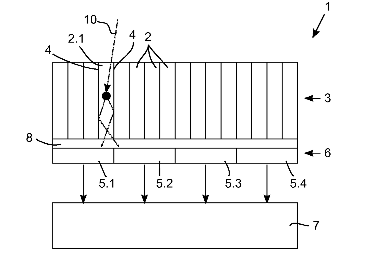
[0050]FIG. 1 illustrates a radiation particle detector 1 employed in a nuclear imaging system, e.g. a high-resolution PET scanner. The radiation particle detector 1 comprises a pixellated scintillator with a plurality of scintillator element locations, wherein the scintillator element locations are scintillator elements 2. The material of the scintillator elements 2 is selected to provide a high stopping power for 511 keV gamma rays with rapid temporal decay of the scintillation burst. Some suitable scintillator materials are lutetium oxyorthosilicate (LSO), lutetium yttrium orthosilicate (LYSO) and lanthanum bromide (LaBr). It should be appreciated that scintillator elements 2 made of other materials can be used instead. The structure of the scintillator material may for example be crystalline, polycrystalline, or ceramic. The scintillator elements 2 are arranged in a scintillator layer 3. In order to avoid light sharing between the scintillator elements 2 a reflector material 4, e...

second embodiment

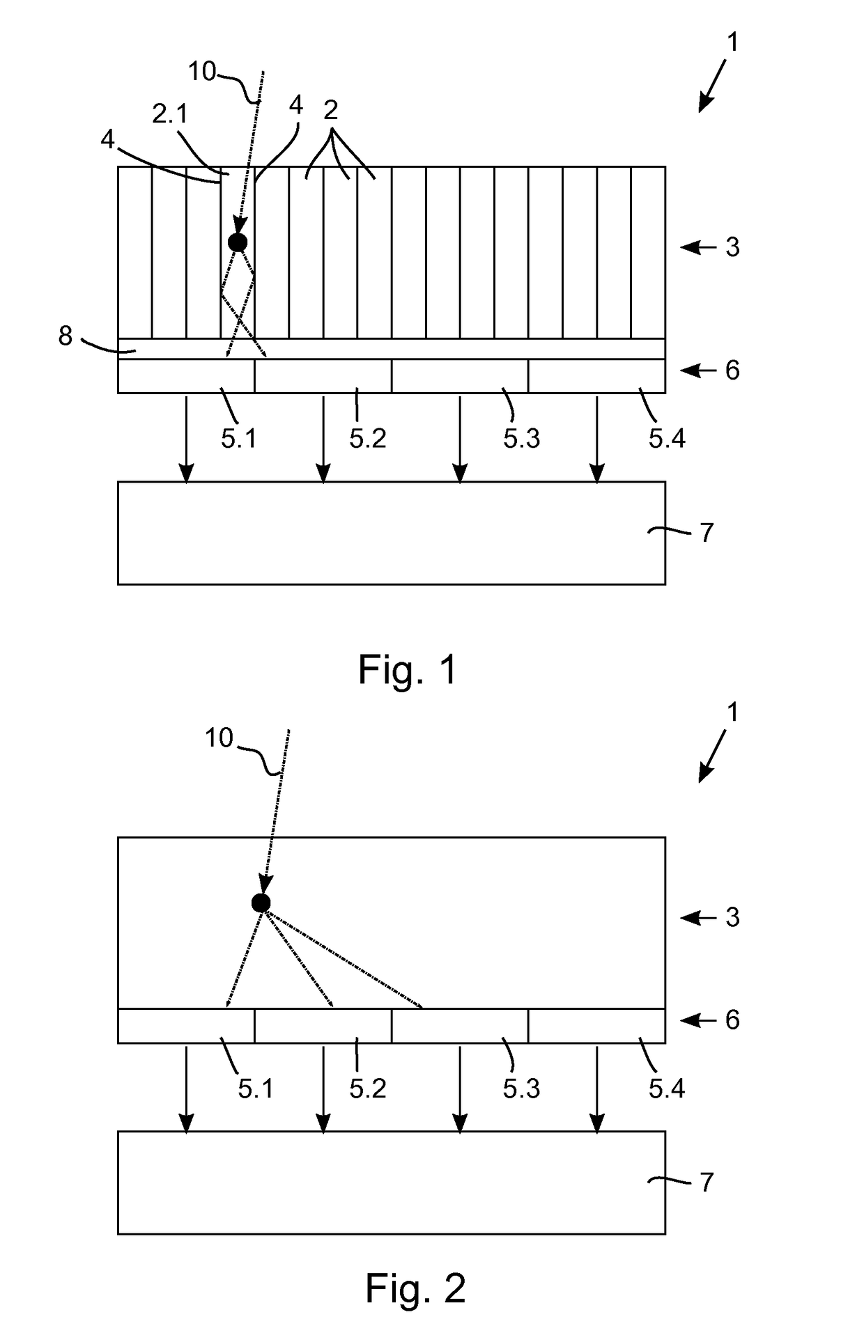
[0061]The radiation particle detector does not comprise a light guide. Nevertheless, a light guide can optionally be disposed between the scintillator layer 3 and the photosensor layer 6 to further enhance light spreading onto the photosensors 5.1, 5.2, 5.3, 5.4.

[0062]FIG. 2 illustrates an interaction of gammy ray 10 with the monolithic scintillator 2 of the scintillator layer 3. Gamma ray 10 is stopped at a scintillator element location and the resulting burst of photons is spread over three neighboring photosensors 5.1, 5.2, 5.3.

[0063]The position as well as the energy of a scintillation event in the radiation particle detector according to the second embodiment may be determined as described with reference to the first embodiment.

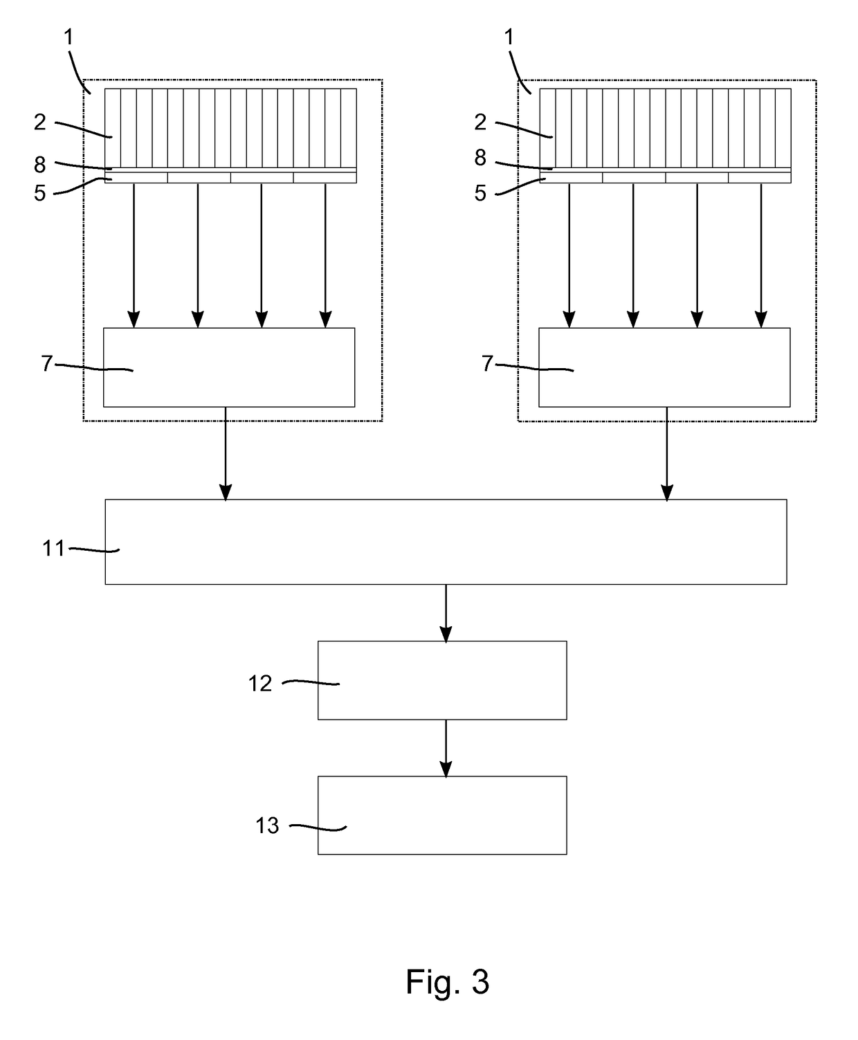
[0064]FIG. 3 is a diagrammatic illustration of a nuclear imaging system configured as a PET scanner including a plurality of radiation particle detectors 1. The radiation particle detectors 1 are arranged in one or more rings along an axial direction; h...


PUM


Abstract

A method for determining the position of a scintillation event in a radiation particle detector with multiple scintillator element locations which are configured to emit a burst of photons responsive to a radiation particle being absorbed at the scintillator element location and with a plurality of photosensors (5.1, 5.2, 5.3, 5.4) optically coupled to said scintillator element locations, comprising the steps of determining, for each of the photosensors (5.1, 5.2, 5.3, 5.4), a triggering probability indicative of the probability of said photosensor (5.1, 5.2, 5.3, 5.4) measuring a number of photons that exceeds a predetermined triggering threshold; measuring a photon distribution with the photosensors (5.1, 5.2, 5.3, 5.4) indicative of the number of photons incident on the individual photosensors (5.1, 5.2, 5.3, 5.4); calculating, for each of the scintillator element locations, a likelihood that a scintillation event with a predetermined energy value took place in said scintillator element location based on the measured photon distribution and the triggering probability of each of the photosensors (5.1, 5.2, 5.3, 5.4); and identifying the scintillator element location having the maximum likelihood.

Description

FIELD OF THE INVENTION[0001]The present invention relates to the field of radiation particle detectors. It finds particular application in nuclear imaging systems such as, for example positron emission tomography (PET) scanners for clinical or research studies as well as single photon emission computed tomography (SPECT) scanners.BACKGROUND OF THE INVENTION[0002]In PET scanners pixellated scintillator elements are typically used to convert incident radiation particles to bursts of photons with a wavelength in the UV or visible spectrum. The scintillator elements are typically arranged in a matrix wherein each scintillator element has a base area in the order of 1×1 mm2 to 4×4 mm2. The scintillation events are detected by photosensors coupled to the scintillator elements. State of the art PET scanners use solid-state photosensors, e.g. silicon photomultipliers (SiPMs), typically comprising an array of single photon avalanche diodes (SPADs) being configured to break down responsive to...

Claims


Application Information

Patent Timeline
Patent Type & Authority Applications(United States)
IPC IPC(8): G01T1/29G01T1/164G01T1/20G01R33/48G01T1/16G01T1/24
CPCG01T1/2985G01T1/1647G01T1/20G01T1/243G01R33/481G01T1/1603G01T1/1642
Inventor BERKER, YANNICKSCHULZ, VOLKMAR
Owner KONINKLJIJKE PHILIPS NV
Learn More