Layerless bioprinting via dynamic optical projection and uses thereof

a bioprinting and optical projection technology, applied in the field of three-dimensional structure microfabrication, can solve the problems of inability to achieve speed and scalability well, and achieve the effects of high resolution, high resolution and rapid generation of polymeric scaffolds

Active Publication Date: 2017-03-30
RGT UNIV OF CALIFORNIA
View PDF4 Cites 36 Cited by
  • Summary
  • Abstract
  • Description
  • Claims
  • Application Information

AI Technical Summary

Benefits of technology

[0012]In an exemplary embodiment, a method and system are provided for rapid generation of polymeric scaffolds with highly specified 3D geometries. The inventive biofabrication method is referred to herein as “Layerless 3D Printing via Dynamic Optical Projection”, or “L3PDOP”. The inventive L3PDOP 3D printing system and method can receive an input comprising a 3D computer-generated model and from that model generate the structure in a variety of photopolymerizable materials with high resolution. The inventive 3D printing system uses a dynamically controlled DMD (digital micromirror device) to reflect a high resolution pattern of UV light onto a photopolymerizable substrate. Integration with custom computer software allows for the simultaneous and continuous control of the projected image and the linear stage that controls the position of the substrate in relation to the focal plane of projected light. Due to the continuous movement of the stage, the fabricated 3D structures have smooth (i.e., layerless) contours in the Z (vertical) direction. By controlling the composition of the pre-polymer solution, for example, by inclusion of naturally-derived and / or synthetic biomaterials, bioactive molecules, heterogeneous cell populations, 3D structures that mimic native tissue environments can be created within seconds. Additionally, rapid control of the micromirror array provides for micron and sub-micron level changes in local material properties (such as porosity and material stiffness) via spatiotemporal patterning of transient UV exposure throughout the polymer.
[0014]The inventive method and system provide a novel stereolithographic approach via dynamic continuous control of a micromirror array (DMD) along with a linear stage. Specifically, the device allows for an improvement over the state of the art due to its speed, scalability, and layerless Z resolution. By providing layerless resolution, the fabricated structures do not exhibit the planar artifacts produced using traditional layer-by-layer fabrication approaches that involve discrete movement of the linear stage to a new height position. Furthermore, the inventive L3PDOP 3D printing platform provides for rapid and scalable fabrication of highly-specified biomimetic structures. This approach provides capability in terms of speed and scalability that cannot be well-achieved using existing technologies that employ raster-based printing approaches or soft lithography techniques. Additionally, as the L3PDOP system can accept virtually any set of high-detail images, this platform provides a method for generating models with specificity not only in terms of cell type but also whole tissue morphology. The flexibility of the platform allows for the modular addition and subsequent decoupling of various components of a complex 3D construct, providing a means to determine the individual contributions of material type, co-culture populations, spatial cell arrangements, and biomimetic geometries. Modes of operation for the apparatus include 3D microscale bioprinting of biological substrates via dynamic stereolithography, and optogenetic control of neurons with high spatiotemporal resolution, along with accompanying integrated capabilities for simultaneous electrophysiology and fluorescence imaging. Stereolithographic 3D bioprinting allows for photopolymerization of multiple biocompatible materials (e.g., PEGDA, MeHA, GelMA) and facilitates cell encapsulation within these structures. Additionally, these materials—along with their incorporated cell types—can be used heterogeneously in the same scaffold to provide 3D patterned co-culture substrates, thus facilitating the study of interactions among multiple cell phenotypes, e.g., neuronal / glial interactions.
[0015]As individual pixels of the micromirror array can be switched on and off rapidly throughout the fabrication process, highly localized (e.g., submicron) changes in polymer structure in terms of porosity or material stiffness can be achieved through the spatiotemporal control of pixel-level UV exposure. This platform addresses limitations in the field by allowing simultaneous control over scaffold composition, microstructure, and larger scale 3D geometry as well as providing improvements in speed and scalability.
[0016]In one aspect of the invention, a pre-polymer solution containing free-radical absorbers to inhibit light-activated free-radical polymerization / cross-linking is used to limit the curing depth. A surface treatment may be applied to the window, which may be composed of sapphire or glass (or any other sufficiently rigid optically-transparent material), to prevent polymerization / adhesion of the structure onto the immersed window. This is in contrast to the Carbon3D approach, with printing using the inventive platform occurring directly onto the floor of the bath as opposed to on an immersed probe. This allows the rapid printing of 3D structures within each well of a multi-well plate as the plate is translated within X-Y axes to move from well to well. By not relying on a single large bath immersion, each well can contain a different polymer composition and may ultimately hold a different 3D structure.
[0017]In another aspect of the invention, the method and device are operable for recording network activity across multiple domains. For example: 1) multi-electrode arrays (MEAs)—on which the 3D neuron network structures (or any electrically active cell type) are printed—allow orthogonal recording of electrical activity concurrent with optogenetic stimulation; and 2) fluorescent imaging of voltage-sensitive dyes and proteins, which provides enhanced single-cell resolution of network activity, can be simultaneously performed by employing the same or similar light source utilized for bioprinting.
[0018]In one application of the inventive 3D printing method and system, a brain-on-a-chip is generated by integrating 3D heterogeneous neural cultures, optogenetics-enabled high-resolution stimulation, and parallel electrical and image-based recording of neural activity. The fabrication methods utilized in this platform offer control over both the topographical complexity and the cellular and material composition of the neural environment, thereby allowing for the potential for systematically-controlled increases in complexity.

Problems solved by technology

This approach provides capability in terms of speed and scalability that cannot be well-achieved using existing technologies that employ raster-based printing approaches or soft lithography techniques.

Method used


Image

  • Layerless bioprinting via dynamic optical projection and uses thereof
  • Layerless bioprinting via dynamic optical projection and uses thereof
  • Layerless bioprinting via dynamic optical projection and uses thereof

Examples


example 1

Brain-on-a-Chip

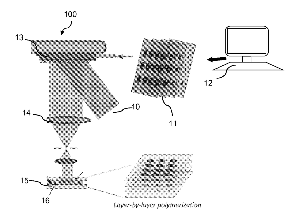
[0084]The L3PDOP platform described above yields two powerful modes of operation, which are diagrammatically illustrated in FIG. 7. The first modality 72 provides for 3D microscale bioprinting of biological substrates via dynamic stereolithography. The second modality 74 provides for optogenetic control of neurons with high spatiotemporal resolution. Stereolithographic 3D bioprinting (mode 72) using the printing platform described with reference to FIG. 1A and FIGS. 2A-2C provides for photopolymerization of multiple biocompatible materials (e.g., PEGDA, MeHA, GelMA) and facilitates cell encapsulation within these structures. Additionally, these materials—along with their incorporated cell types—can be used heterogeneously in the same scaffold to provide 3D patterned co-culture substrates, thus facilitating the study of neuronal / glial interactions.

[0085]Importantly, the inventive platform is capable of functioning not only in the fabrication and optogenetic stimulation...

example 2

Neural Clusters from iPSCs

[0088]The inventive L3PDOP platform finds myriad applications in fundamental neuroscience research, clinical diagnostics, screening of novel drug candidates, and comparative investigations of artificial versus biological neural networks in conjunction with neuromorphic hardware (e.g. “brain-on-a-chip” devices). The inventive printing technique enables facile, rapid fabrication of 3D hydrogels that support the culture of iPSC-derived neurons with the following capabilities: 1) 3D patterning of hydrogel microenvironments via dynamic optical stereolithography for high-throughput scaffold fabrication that is co-registered with MEAs at high precision; 2) directed arrangement of neural clusters and modulation of cell alignment, growth, and connectivity via hydrogel composition, geometry, and dimensions; 3) support for functional connectivity as demonstrated by positive expression of associated biomolecular markers, and 4) spontaneous electrical activity during lo...

example 3

Integration with 3D-Printed Conductive Polymer Electrodes

[0094]High-density 3D recording of the neural network can be achieved by using the stereolithographic technique presented herein to incorporate biocompatible conductive polymers, such as PANI-PAAMPSA, at precise spatial arrangements to transmit neural electrical signals to the multi-electrode array (MEA) substrate. FIGS. 21A and 21B illustrate one possible spatial arrangement and varying electrode lengths, respectively. FIG. 21A shows a simple grid-like array in MEA 210, with uniformly spaced rows and columns of flat electrodes of similar heights, while FIG. 21B illustrates electrodes 212A-n of different lengths (heights) extending from the same grid. As will be readily apparent to those in the art, different geometrical layouts and varying electrode heights can be constructed by selection of appropriate printing patterns, conditions, and materials. Compared to conventional flat electrodes on MEAs, which can directly access on...


PUM

PropertyMeasurementUnit
strain rateaaaaaaaaaa
depthsaaaaaaaaaa
depthsaaaaaaaaaa

Abstract

A system and method for 3D microfabrication projects light capable of initiating photopolymerization toward a spatial light modulator that modulates light responsive to digital masks corresponding to layers of the structure. Projection optics focus the modulated light onto an optical plane within a photopolymerizable material supported on a stage. A computer controller causes the spatial light modulator to project a sequence of images corresponding to the digital masks while coordinating movement of the stage to move a position of the optical plane within the photopolymerizable material to sequentially project each image of the sequence to generate the structure by progressively photopolymerizing the photopolymerizable material.

Description

RELATED APPLICATIONS[0001]The present application claims the benefit of the priority of U.S. Provisional Application No. 62 / 001,025, filed May 20, 2014, which is incorporated herein by reference in its entirety.GOVERNMENT RIGHTS[0002]This invention was made with government support under Grant No. EB012597 awarded by the National Institutes of Health. The government has certain rights in the invention.FIELD OF THE INVENTION[0003]The present invention relates to a method for microfabrication of three-dimensional structures in photopolymers and fabricating biological scaffolds with smooth (layerless) contours.BACKGROUND OF THE INVENTION[0004]Traditional cell culture is usually carried out in a Petri dish, and most commonly used cell biological techniques rely on the use of cultured cells on 2D platforms. As is known, the mechanical properties of cell substrates affect cell differentiation, growth and motility. Thus, the mechanical properties of a material are important to consider when...

Claims


Application Information

Patent Timeline
Patent Type & Authority Applications(United States)
IPC IPC(8): B29C67/00B33Y10/00G01N33/50B33Y50/02B33Y70/00B33Y80/00B29C35/08B33Y30/00
CPCB29C67/007B29L2031/7532B29C67/0092B29C35/0894B29C35/0805B33Y10/00B33Y30/00B33Y50/02B33Y70/00B33Y80/00G01N33/5058G01N33/502B29C2035/0827B29C2035/0838B29K2995/0056B29K2995/0005B29L2031/752B29C67/0088B29C64/129B29C64/386B29C64/40B29C64/277
Inventor CHUNG, PETERQU, XINZHANG, APINGCHEN, SHAOCHEN
Owner RGT UNIV OF CALIFORNIA
Why Eureka
Try Eureka