
Battery pack lock mechanism and battery pack with the mechanism

a battery pack and lock mechanism technology, applied in the direction of batteries/cells, cell components, battery/cell propulsion, etc., can solve the problems of not being able to solve the problem of any existing swappable battery pack, affecting the safety of driving, and putting a lot of pressure on domestic fuel oil supply, so as to prevent the loss of the battery pack, replace the battery pack quickly and conveniently, and install the battery pack safely and reliably

Inactive Publication Date: 2018-03-01
NIO CO LTD
View PDF7 Cites 12 Cited by
  • Summary
  • Abstract
  • Description
  • Claims
  • Application Information

AI Technical Summary

Benefits of technology

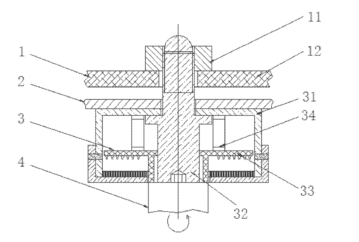
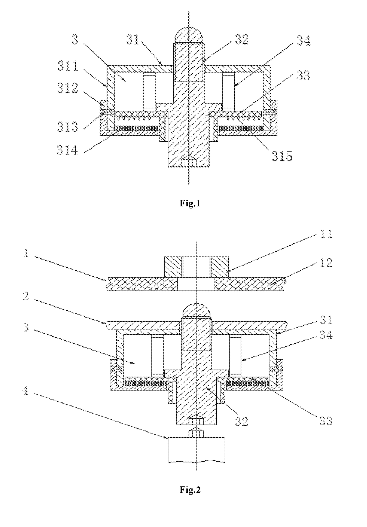
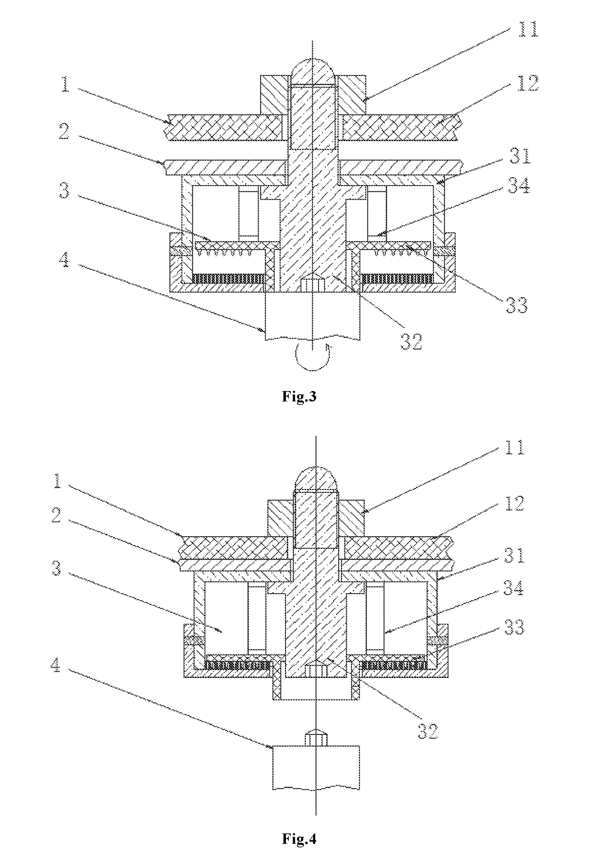
The present patent describes a lock mechanism for a battery pack that is safe, reliable, quick, and convenient to replace. The lock mechanism also prevents the battery pack from becoming loose during long periods of vehicle body vibration.

Problems solved by technology

An increasing number of vehicles in use bring about great pressure on domestic fuel oil supply.
Power battery is the only power source of an electric-only vehicle, which is usually swapped by automation equipments due to its heavy weight as well as backbreaking manual labor and risk of hand operation.
If things continue in this way, many serious problems, such as local deformation of battery packs, deformation of suspension points on vehicle bodies, local wear of the locking devices as well as arc discharge and burning arc of electric connector, may be resulted in, severely endangering safe driving.
Previously described problems can't be resolved by any existing swappable battery packs.

Method used


Image

  • Battery pack lock mechanism and battery pack with the mechanism
  • Battery pack lock mechanism and battery pack with the mechanism
  • Battery pack lock mechanism and battery pack with the mechanism

Examples


Embodiment Construction

[0024]The preferred embodiments of the present application will be described below with reference to the accompanying figures. As will be understood by those skilled in the art, these embodiments are simply used for interpreting the technical principle of the present application and are not intended to limit its protection scope in any way. For example, although each member in the figures is drawn to scale, this proportional relation is merely exemplary in nature and can be modified as desired to accommodate specific applications by those skilled in the art.

[0025]It should be noted that in the description of the present application, the usage of such directional and positional terms as ‘central’, ‘upper’, ‘lower, ‘left’, ‘right’, ‘vertical’, ‘horizontal’, ‘inner’ and ‘outer’, is based on the directional and positional relations shown in the drawings, and used to facilitate the description itself and does not express or imply the necessary specific positions or specific operational a...


PUM

PropertyMeasurementUnit
weightaaaaaaaaaa
shapeaaaaaaaaaa
sizeaaaaaaaaaa

Abstract

The present application relates to installation and swap of electric vehicle battery, particularly to a battery pack lock mechanism. The lock mechanism aims at solving the problems that the battery pack is unable to be reliably installed and quickly swapped and to be well protected from loosing during long period of driving. To resolve the above described problems in the prior art, the lock mechanism comprises a housing, a thread bolt, a flange, a spring and a hemp disk assembly which has spike-like protrusions. The flange is unable to rotate around the axis of the bolt, but can slide along its axial direction. The spring can press the flange so that the spike-like protrusions of the flange are engaged with the hemp stopper on the housing, so that the flange and the bolt can't rotate relative to each other, and the bolt can connect the housing to the body of an electric vehicle. Thanks to the previously noted structure, the lock mechanism is not only able to safely and reliably install and quickly and conveniently replace the battery pack, but also able to prevent loosing of the battery pack during long period of vehicle body vibration by means of rigidly fastening the pack.

Description

CROSS-REFERENCE TO RELATED APPLICATION[0001]This application claims the benefit of Chinese Patent Application No. 201610791996.1 filed Aug. 31, 2016, the entire disclosure of which is incorporated herein by reference.TECHNICAL FIELD[0002]The present application relates to installation and swap of electric vehicle battery, particularly to a battery pack lock mechanism and a battery pack with such a lock mechanism.BACKGROUND[0003]As a country relatively short of petroleum, China has to import a great deal of crude oil and product oil. An increasing number of vehicles in use bring about great pressure on domestic fuel oil supply. Widely promoting electric vehicles will not only bring benefit to national security of petroleum and energy resources but also make us rely less on import of vehicle oil. Therefore, development of electric vehicles is an important strategic choice guaranteeing sustainable growth of vehicle industry.[0004]A beneficial supplement to battery recharging is to repl...

Claims


Application Information

Patent Timeline
Patent Type & Authority Applications(United States)
IPC IPC(8): H01M2/10B60L11/18B60L50/64H01M50/249
CPCH01M2/1083H01M2220/20B60L11/1879B60L11/1822B60K1/04H01M50/262B60L50/64H01M50/249B60L53/80Y02T10/70Y02T10/7072Y02E60/10
Inventor HAO, ZHANDUO
Owner NIO CO LTD
Learn More