
Tamper proof circuit for surgical instrument battery pack

Active Publication Date: 2018-03-08
CILAG GMBH INT
View PDF49 Cites 501 Cited by
  • Summary
  • Abstract
  • Description
  • Claims
  • Application Information

AI Technical Summary

Benefits of technology

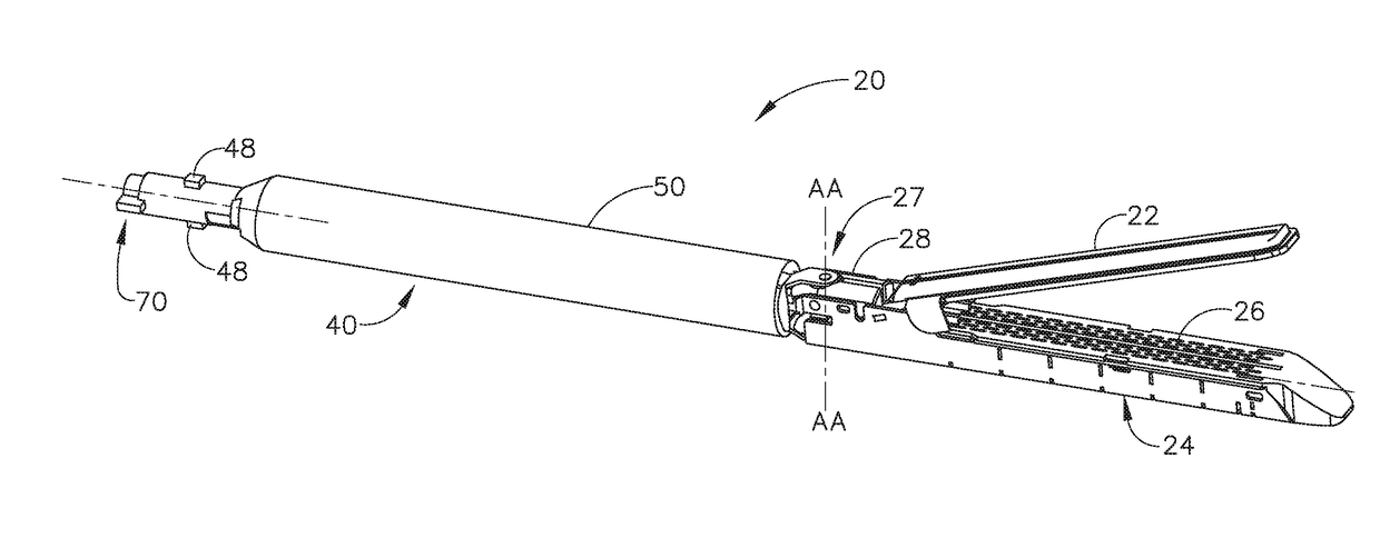
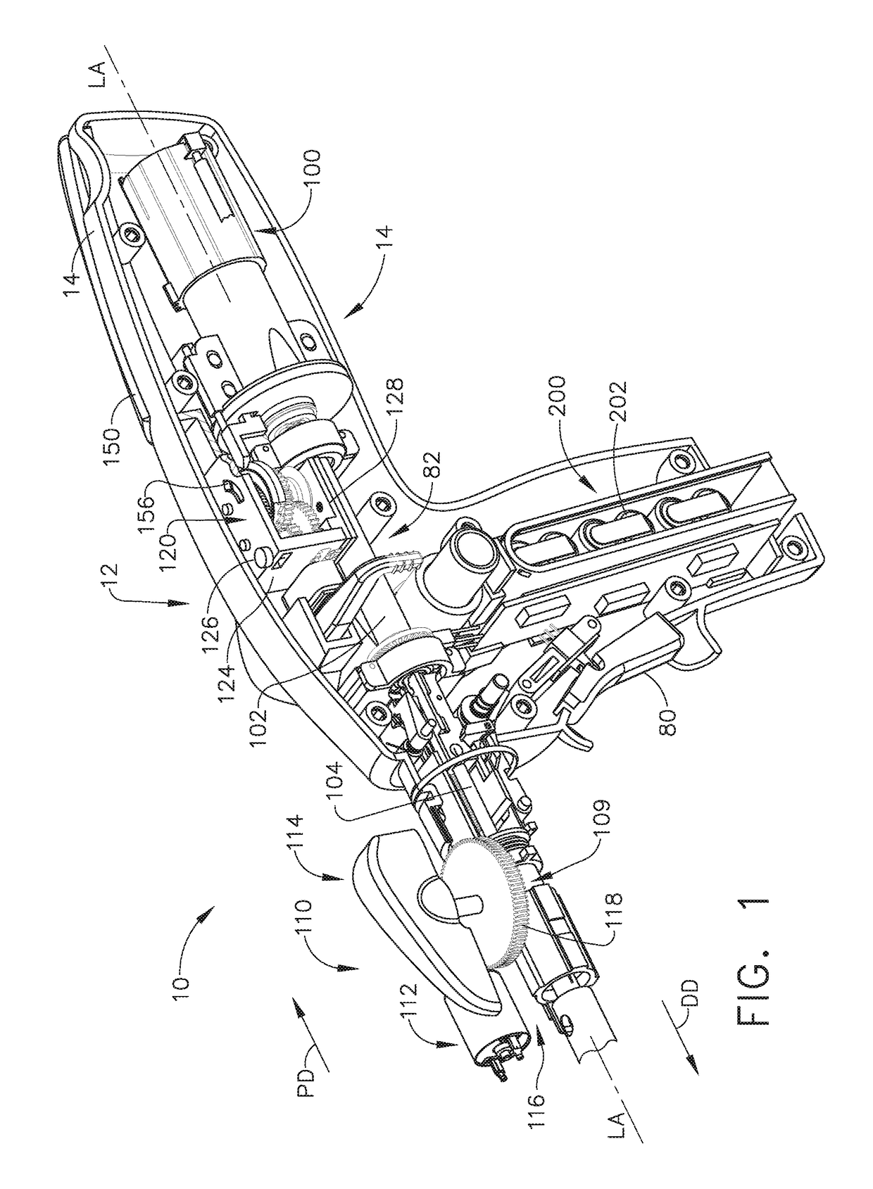
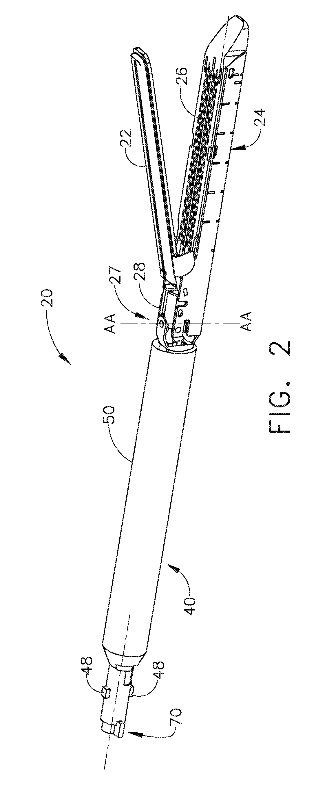
The present invention is related to surgical instruments and, in particular, to powered surgical cutting and stapling instruments. The invention aims to provide a surgical instrument with a tamper-proof circuit that can prevent unauthorized access or malicious tampering. The invention includes a retraction arrangement for the end effector of the surgical instrument, which can be activated to secure the soft tissue between the jaw members. The end effector can also include a cutting member for resecting the soft tissue after the layers have been stapled together. The invention also includes a loading unit that can be used with various surgical instruments to facilitate their use. The technical effects of the invention include improved security and reliability of the surgical instrument, as well as improved efficiency and ease of use.

Problems solved by technology

If a surgeon is unsatisfied with the position of the end effector, however, the surgeon must typically activate a release mechanism on the surgical stapler to pivot the anvil into an open position and then reposition the end effector.

Method used


Image

  • Tamper proof circuit for surgical instrument battery pack
  • Tamper proof circuit for surgical instrument battery pack
  • Tamper proof circuit for surgical instrument battery pack

Examples


Embodiment Construction

[0195]Applicant of the present application also owns the following patent applications that were filed on Aug. 23, 2013 and which are each herein incorporated by reference in their respective entireties:[0196]U.S. patent application Ser. No. 13 / 974,166, entitled FIRING MEMBER RETRACTION DEVICES FOR POWERED SURGICAL INSTRUMENTS, now U.S. Pat. No. 9,700,310.[0197]U.S. patent application Ser. No. 13 / 974,215, entitled SECONDARY BATTERY ARRANGEMENTS FOR POWERED SURGICAL INSTRUMENTS, now U.S. Patent Application Publication No. 2015 / 0053748.[0198]U.S. patent application Ser. No. 13 / 974,202, entitled ERROR DETECTION ARRANGEMENTS FOR SURGICAL INSTRUMENT ASSEMBLIES, now U.S. Patent Application Publication No. 2015 / 0053743.[0199]U.S. patent application Ser. No. 13 / 974,205, entitled ATTACHMENT PORTIONS FOR SURGICAL INSTRUMENT ASSEMBLIES, now U.S. Patent Application Publication No. 2015 / 0053740.[0200]U.S. patent application Ser. No. 13 / 974,169, entitled CLOSURE INDICATOR SYSTEMS FOR SURGICAL INS...


PUM


Abstract

A surgical instrument includes a shaft, an end effector extending distally from the shaft, and a housing extending proximally from the shaft. The housing includes a motor configured to generate at least one motion to effectuate the end effector, and a power source configured to supply power to the surgical instrument, wherein the power source includes a casing, a data storage unit, and a deactivation mechanism configured to interrupt access to data stored in the data storage unit. In addition, the power source includes a battery pack and a deactivation mechanism configured to deactivate the battery pack if the casing is breached.

Description

CROSS REFERENCE TO RELATED APPLICATION[0001]This application is a continuation application claiming priority under 35 U.S.C. §120 to U.S. patent application Ser. No. 13 / 974,224, entitled TAMPER PROOF CIRCUIT FOR SURGICAL INSTRUMENT BATTERY PACK, filed on Aug. 23, 2013, now U.S. Patent Application Publication No. 2015 / 0053741, the entire disclosure of which is hereby incorporated by reference herein.FIELD OF THE INVENTION[0002]The present invention relates to surgical instruments and, in various arrangements, to powered surgical cutting and stapling instruments and staple cartridges therefor that are designed to cut and staple tissue.BACKGROUND[0003]Surgical staplers are often used to deploy staples into soft tissue to reduce or eliminate bleeding from the soft tissue, especially as the tissue is being transected, for example. Surgical staplers, such as an endocutter, for example, can comprise an end effector which can be moved, or articulated, with respect to an elongated shaft asse...

Claims


Application Information

Patent Timeline
Patent Type & Authority Applications(United States)
IPC IPC(8): A61B17/072G09G5/14H02J7/00A61B17/00A61B17/068G06F3/041G06F3/0488G06F19/00G06F21/60G06T11/60G06F3/01
CPCG16H40/63A61B2034/252A61B2017/07285A61B17/07207A61B17/00234A61B17/068A61B17/072A61B34/25G06F3/016G06F3/0416G06F3/0488G06F19/3406G06F21/60G06T11/60G09G5/14H02J7/0068A61B2017/00017A61B2017/00137A61B2017/00199A61B2017/00367A61B2017/00398A61B2017/00402A61B2017/00734A61B2017/07271A61B2034/256A61B2017/00477A61B2017/00473H01M10/48A61B34/30H03K2217/96062A61B2090/0808A61B2090/0811A61B2017/00119A61B2017/00154A61B2017/0019A61B2017/00221A61B2017/00407A61B2017/00482A61B90/90A61B90/96A61B90/98A61B2090/0807A61B34/10H01M10/425H01M2220/30A61B2017/00486A61B2090/0804A61B34/74A61B34/76A61B2017/2927A61B2017/00084A61B2017/00115A61B2017/00123A61B2017/07214A61B2017/2923A61B2017/2929A61B2017/2941A61B2017/2946A61B2017/00464A61B2017/291A61B2560/0214H02J7/342H02J2310/23H02J9/061Y02E60/10A61B2090/037G16H20/40A61B90/37A61B2090/035A61B2090/0803A61B2090/0814A61B2090/372A61B2034/254G06F3/04817G06F3/0482G06F3/04845G16Z99/00A61B2017/0046A61B2017/2901A61B2017/07228A61B17/105A61B2017/07257A61B2017/07278A61B90/03H02J7/00
Inventor SHELTON, IV, FREDERICK E.SCHELLIN, EMILY A.YATES, DAVID C.HOUSER, KEVIN L.
Owner CILAG GMBH INT
Learn More