Granular material, three-dimensional laminated and shaped mold, three-dimensional laminated and shaped mold manufacturing method, and three-dimensional laminated and shaped mold manufacturing apparatus

Inactive Publication Date: 2018-03-08
TECH RES ASSOC FOR FUTURE ADDITIVE MFG
View PDF3 Cites 2 Cited by
  • Summary
  • Abstract
  • Description
  • Claims
  • Application Information

AI Technical Summary

Benefits of technology

[0021]The present invention can reduce a gas defect as one of casting defects and facilitates reusing

Problems solved by technology

To manufacture a mold having a complicated shape, however, it is necessary to increase the number of models, and this complicates the p

Method used


Image

  • Granular material, three-dimensional laminated and shaped mold, three-dimensional laminated and shaped mold manufacturing method, and three-dimensional laminated and shaped mold manufacturing apparatus
  • Granular material, three-dimensional laminated and shaped mold, three-dimensional laminated and shaped mold manufacturing method, and three-dimensional laminated and shaped mold manufacturing apparatus
  • Granular material, three-dimensional laminated and shaped mold, three-dimensional laminated and shaped mold manufacturing method, and three-dimensional laminated and shaped mold manufacturing apparatus

Examples


Example

Example 1

[0096]A sand mixture in which magnesium sulfate was mixed was prepared as a refractory granular material by using silica sand (FS001-EU distributed by EX ONE, average grain size=106 μm).

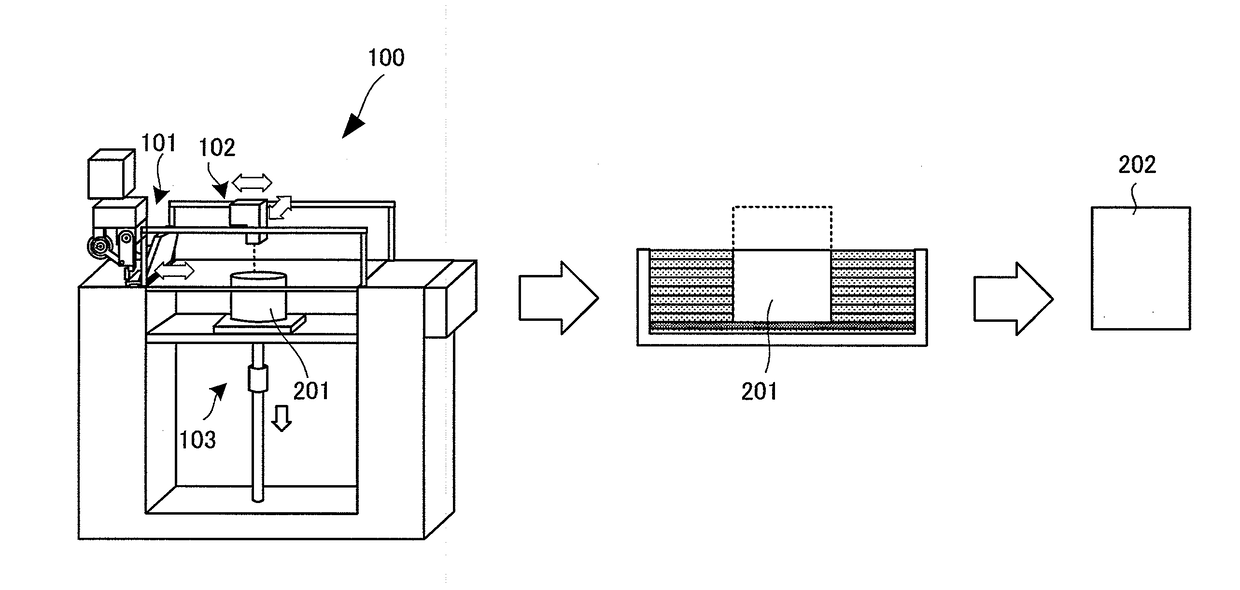
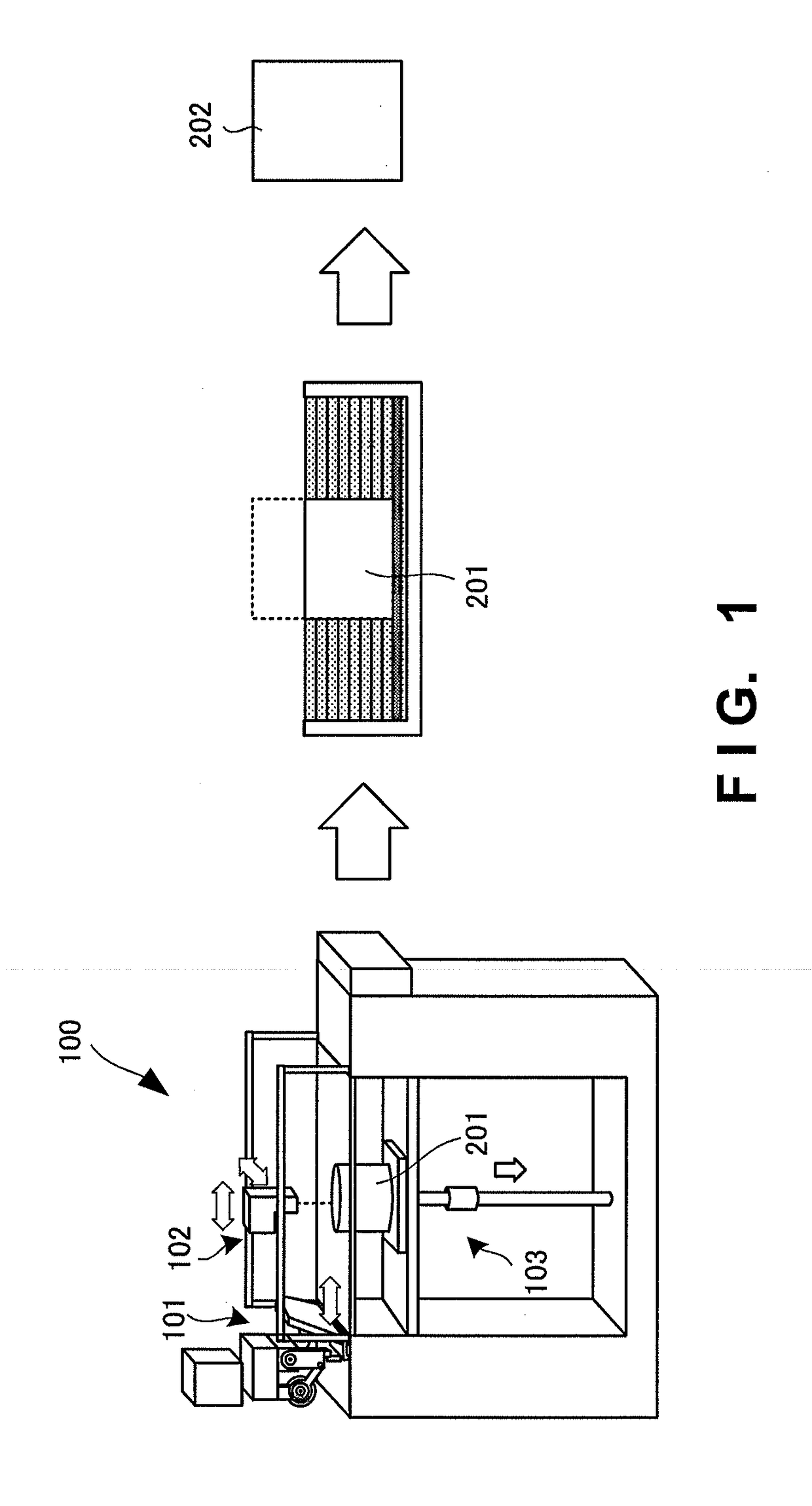
[0097]This refractory granular material was laminated, by a blade mechanism including a recoater, on the bottom surface of a metal case placed in a three-dimensional laminating apparatus (manufactured by CMET) using a printing shaping method.

[0098]Then, a printing nozzle head was scanned on the laminated refractory granular material based on data obtained by 3DCAD design of the shape of a three-dimensional laminated and shaped mold, thereby printing water such that the discharge amount was 10 pts·mass with respect to 100 pts·mass of the laminated sand. After water was printed, the bottom surface (a shaping table) of the metal case was moved down by one layer (280 μm), the refractory granular material was laminated in the same manner as above, and water was printed on it such that the dischar...

Example

Example 2

[0103]Test pieces were manufactured and evaluated following the same procedures as in Example 1, except that coating sand using artificial sand (CERABEADS X #1450 manufactured by ITOCHU CERATECH, average grain size=106 μm) obtained by a sintering method was used as the refractory granular material. Table 1 shows the evaluation results of Example 2.

Example

Example 3

[0104]Coating sand coated with magnesium sulfate was prepared as a refractory granular material by using silica sand (FS001-EU distributed by EX ONE, average grain size=106 μm).

[0105]This refractory granular material was laminated, by a blade mechanism including a recoater, on the bottom surface of a metal case placed in a three-dimensional laminating apparatus (manufactured by CMET) using a printing shaping method.

[0106]Then, a printing nozzle head was scanned on the laminated refractory granular material based on data obtained by 3DCAD design of the shape of a three-dimensional laminated and shaped mold, thereby printing water such that the discharge amount was 10 pts·mass with respect to 100 pts·mass of the laminated sand. After water was printed, the bottom surface (a shaping table) of the metal case was moved down by one layer (280 μm), the refractory granular material was laminated in the same manner as above, and water was printed on it such that the discharge amount...


PUM

PropertyMeasurementUnit
Grain sizeaaaaaaaaaa
Temperatureaaaaaaaaaa

Abstract

Provided is a granular material which generates no harmful gas at the time of pouring, reduces a gas defect as one of casting defects, and is readily reusable after pouring, in the manufacture of a three-dimensional laminated and shaped mold. This granular material is a granular material for use in a three-dimensional laminated and shaped mold manufacturing apparatus, and includes magnesium sulfate. The amount of magnesium sulfate included in the granular material is 1 to 10 pts·mass with respect to 100 pts·mass of the granular material. The amount of water included in the granular material is 0.1 mass % or less except for crystallization water of magnesium sulfate.

Description

TECHNICAL FIELD[0001]The present invention relates to a three-dimensional laminated and shaped mold manufacturing technique.BACKGROUND ART[0002]A mold is necessary to manufacture a cast metal. Examples of the mold are a heat-hardening mold, self-hardening mold, and gas-hardening mold. For example, the self-hardening mold is generally manufactured by a method of filling kneaded sand including a refractory granular material, hardener, and binder in a wooden model or resin model (to be collectively called “a model” hereinafter), and hardening the binder. To manufacture a mold having a complicated shape, however, it is necessary to increase the number of models, and this complicates the process. Also, even when the number of models can be increased, no mold can be manufactured if the models cannot be removed from the mold.[0003]To solve these problems, a mold manufacturing technique using three-dimensional laminating and shaping capable of directly manufacturing a mold without using any...

Claims


Application Information

Patent Timeline
IPC IPC(8): B22C9/10B22C9/12B22C9/02B22C1/18
CPCB22C9/10B22C9/12B22C9/02B22C1/18B33Y10/00B33Y70/00B28B1/001B28B7/346B29C64/165Y02P10/25
Inventor NAGAI, YASUHIROHATORI, YUUKIOOBA, YOSHIKAZUOKANE, TOSHIMITSU
Owner TECH RES ASSOC FOR FUTURE ADDITIVE MFG
Why Eureka
Try Eureka