
Adjustable door strike plate and method of using the same

a technology of adjustable door strike plate and adjustable plate, which is applied in the direction of building locks, construction, building construction, etc., can solve the problems of requiring a fraction of the time to properly install a new or replacement strike plate, premature or overextended, and the plate moved back to its previous (unusual) position, so as to reduce the frustration of mismarking, reduce the time, and avoid premature or overextended.

Inactive Publication Date: 2018-03-08
KAMODY DENNIS +1
View PDF72 Cites 3 Cited by
  • Summary
  • Abstract
  • Description
  • Claims
  • Application Information

AI Technical Summary

Benefits of technology

The present invention is a device and method for installing a strike plate on a doorjamb. The device helps to overcome the frustration of mismarking and reduces the time needed for proper installation. It allows for easy and accurate positioning of the strike plate without any conventional measuring or trial-and-error mounting damage to the doorjamb. The device is cost-effective and easy to install and test for proper location. It results in a better fit of the door, less rattling, and improved energy efficiency. The device also allows for a new method of installing the correct strike plate connectivity position for a given door latch or dead bolt without the risk of a misstep.

Problems solved by technology

It requires a fraction of the time to properly install a new or replacement strike plate, especially when compared to its known alternatives.
If under puttied, or over puttied, moving the strike plate to a new location could result in the moved plate slipping back to its previous (undesired) position.
Wrong putty volumes can also lead to premature or overextended strike plate adhesive, the latter making it more difficult to remove AND move to the next location over time.
Excess adhesive may, in turn, lead to strike plate interference with the doorjamb proper and / or bending / bowing of the strike plate itself.

Method used


Image

  • Adjustable door strike plate and method of using the same
  • Adjustable door strike plate and method of using the same
  • Adjustable door strike plate and method of using the same

Examples


Embodiment Construction

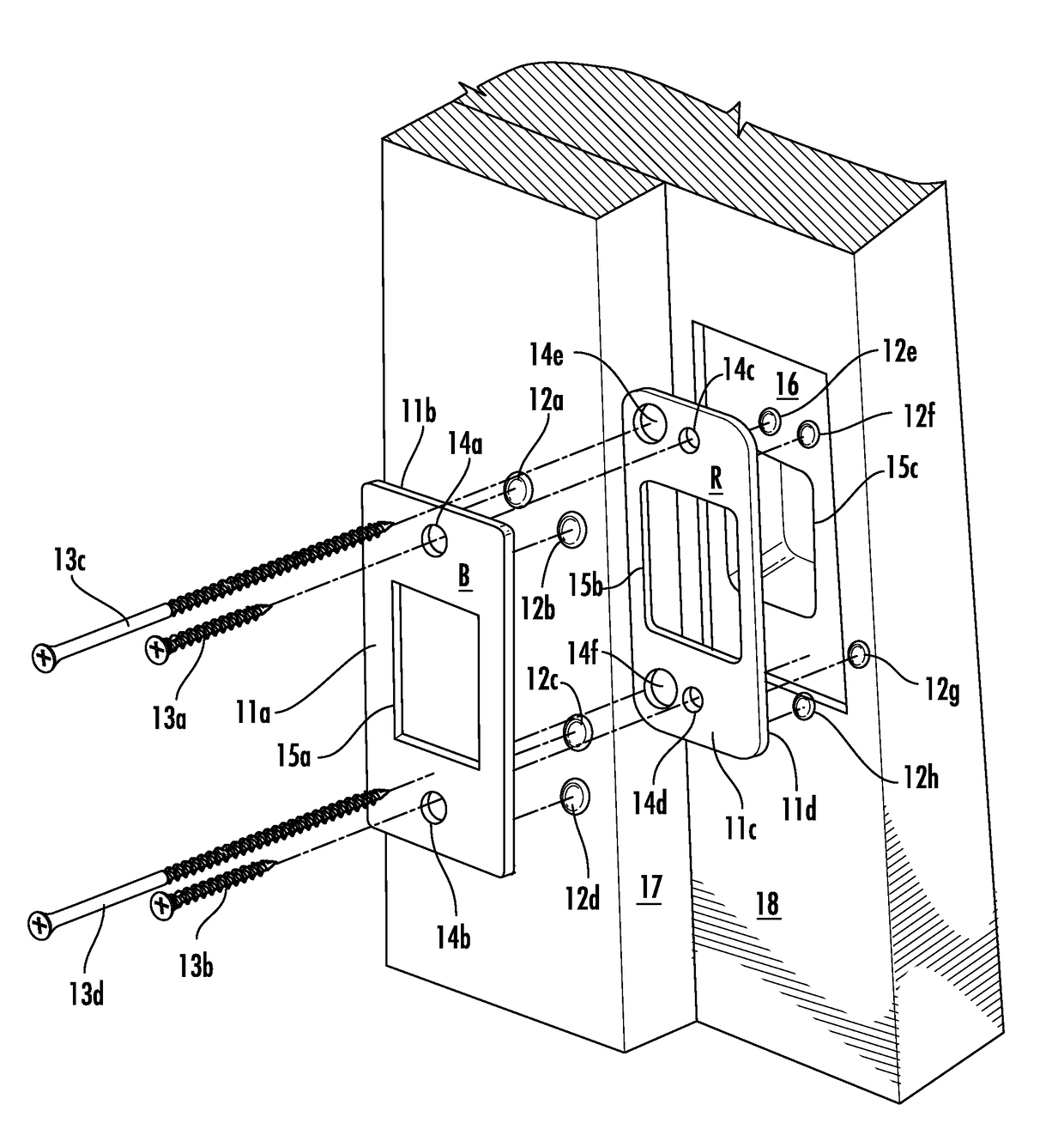
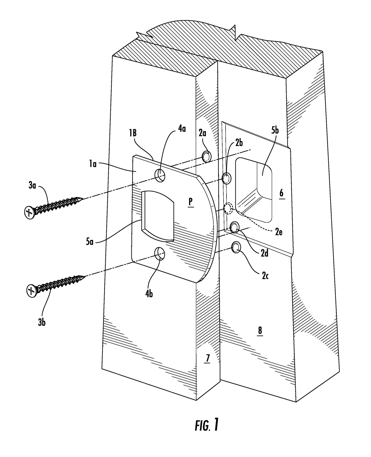
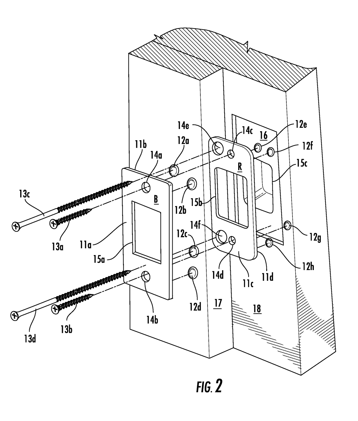
[0036]The device of this invention is comprised of three components: a latch or dead bolt metal strike plate, an adhesive / putty with special properties and applied at preferred quantities, and a plurality of permanent mounting screws. The adhesive / putty is applied to the back face of a strike plate for making the latter mount-adjustable. The device requires an installer's finger pressure to first apply to the surface of a doorjamb and then, after checking whether properly located, sliding to a second (third or more) mounting location if needed.

[0037]The volume amount of special properties adhesive / putty to be used on the back side of a strike plate has a preferred minimum and maximum. If applied at too little volume, or too low in quantity, the strike plate will not be able to be slid / shifted and then held in place at a new, secondary position. Or, it may separate / detach / not stick and fall away from the doorjamb before the final, permanent mounting screws are installed. If applied w...


PUM


Abstract

A door strike plate that can be temporarily mounted to a first location for proper alignment, tested while still temporarily mounted and moved to a second location if the first location is not properly aligned. It comprises a metal strike plate having a plurality of mounting screw holes on either side of a centrally-located latch hole; an appropriately sized dot of an adhesive / putty applied to a region adjacent each mounting screw hole. The door strike plate further includes a permanent mounting screw for each mounting screw hole in the metal strike plate.

Description

CROSS-REFERENCE TO RELATED APPLICATION[0001]This application is a continuation-in-part of U.S. patent application Ser. No. 14 / 690,457, filed on Apr. 19, 2015, the disclosure of which is fully incorporated by reference herein.BACKGROUND OF THE INVENTION[0002]When installing door lock sets, the location where the strike plate or dead bolt plate gets positioned to a wooden door jam can be critical. Both amateurs and professional door installers have a propensity to miss the correct strike plate location when securing with screws to complete the installation. The less skilled the installer, the higher the propensity to “miss”. Even a highly skilled installer may not find the best strike plate installation fit on his / her first attempt.[0003]The propensity to miss finding a satisfactory, if not ideal, strike plate location before fastening the same with screws is challenging when installing a lock set on a new construction or when replacing one existing lock set with another. This is due ...

Claims


Application Information

Patent Timeline
Patent Type & Authority Applications(United States)
IPC IPC(8): E05B15/02
CPCE05B15/024E05B15/0245E05B17/0004
Inventor KAMODY, DENNISWELSH, CANDICE KAMODY
Owner KAMODY DENNIS
Learn More