Optical measurement method and optical measurement apparatus

a measurement method and optical measurement technology, applied in the direction of optical radiation measurement, instruments, spectrometry/spectrophotometry/monochromators, etc., can solve the problems of complex process for obtaining correction reference data, complicated step of creating linearization data, and time-consuming calibration. , to achieve the effect of enhancing the accuracy of output linearity and reducing the time and effort of calibration

Active Publication Date: 2018-03-15
OTSUKA DENSHI CO LTD
View PDF0 Cites 2 Cited by
  • Summary
  • Abstract
  • Description
  • Claims
  • Application Information

AI Technical Summary

Benefits of technology

The patent text is about a way to measure things using optics that saves time and effort in calibration and produces more accurate results.

Problems solved by technology

However, preparation of the three types of detectors is required, and Japanese Patent Laying-Open No. 2006-23284 does not teach improvement in output linearity of each detector.
Such step of creating the linearization data is complicated.
As described above, the process for obtaining the correction reference data is complicated.

Method used


Image

  • Optical measurement method and optical measurement apparatus
  • Optical measurement method and optical measurement apparatus
  • Optical measurement method and optical measurement apparatus

Examples


Embodiment Construction

[0035]An embodiment of the present invention will be described in detail with reference to the drawings, in which the same or corresponding portions are denoted by the same reference characters and description thereof will not be repeated.

[0036]

[0037]First, an apparatus configuration of an optical measurement system including an optical measurement apparatus according to the present embodiment will be described.

[0038](a1: Optical Measurement System)

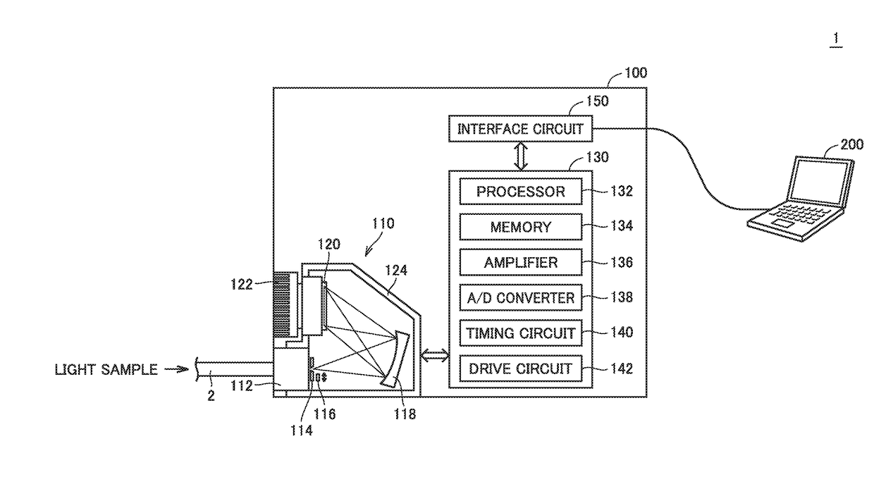
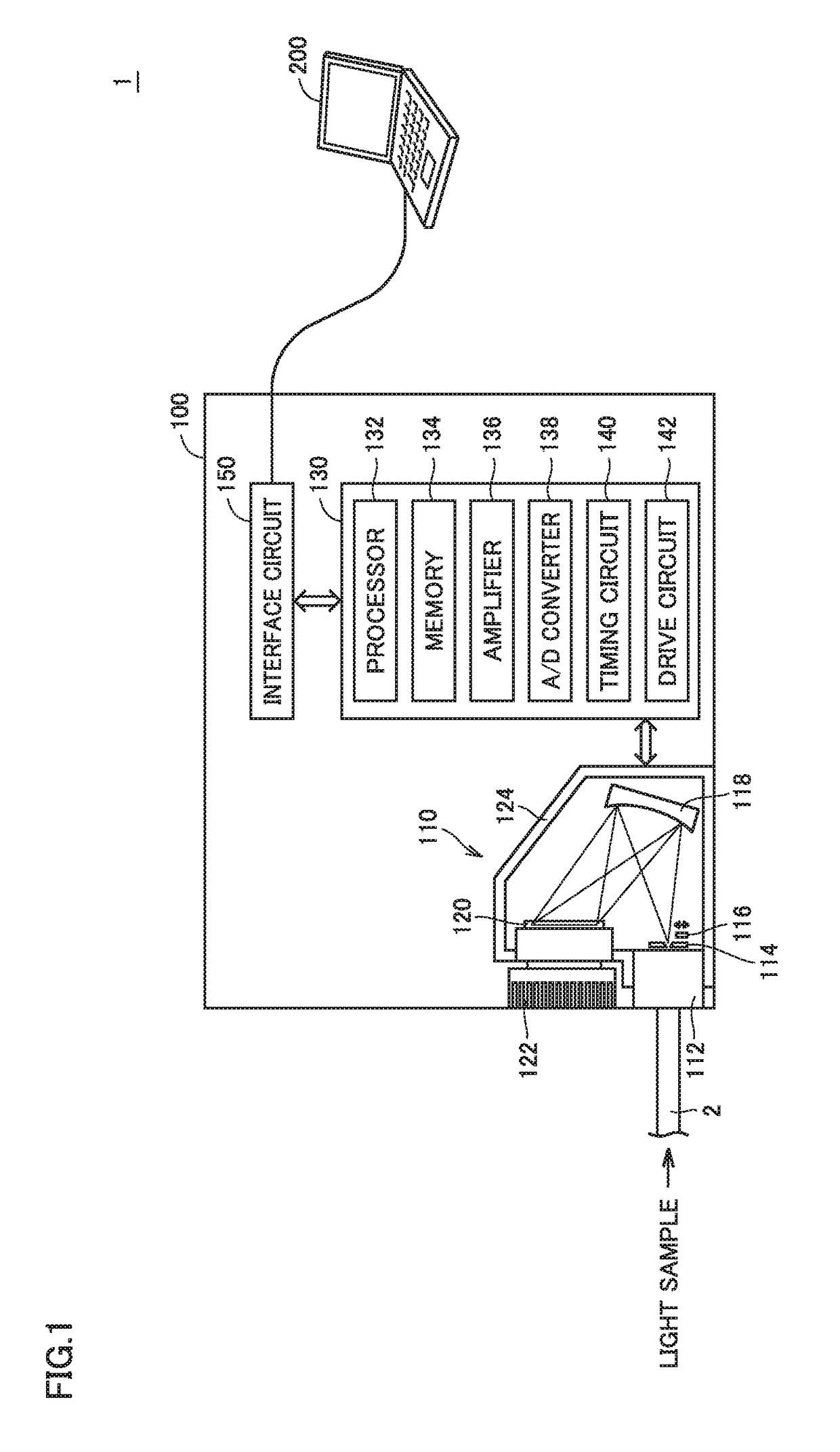
[0039]Referring to FIG. 1, an optical measurement system 1 includes an optical measurement apparatus 100 and a processing apparatus 200. Optical measurement system 1 may further include a printer configured to print out a measurement result and the like. Although FIG. 1 shows the example in which optical measurement apparatus 100 and processing apparatus 200 are separated from each other, these apparatuses may be integrally formed. Alternatively, a plurality of optical measurement apparatuses 100 may be controlled by single processing app...


PUM


Abstract

There is provided an optical measurement method using a detector having a detection sensitivity to at least a near-infrared region. The optical measurement method including: obtaining an output value by measuring a light sample at any exposure time with the detector; and correcting the output value with an amount of correction corresponding to the output value, when the exposure time at which the output value is obtained is within a second range. The amount of correction includes a product of a coefficient and a square of the exposure time, the coefficient indicating a degree to which an output value obtained when the light sample is measured with the detector at an exposure time within the second range deviates from output linearity obtained when the light sample is measured with the detector at an exposure time within a first range.

Description

BACKGROUND OF THE INVENTIONField of the Invention[0001]The present invention relates to an optical measurement method and an optical measurement apparatus that can enhance the measurement accuracy.Description of the Background Art[0002]A configuration of receiving light from a sample at a detector is used in a general optical characteristic measurement system. In order to enhance the measurement accuracy, it is preferable that there is a stable correspondence relation (particularly, output linearity) between the intensity of the light incident on the detector and the signal level output from the detector.[0003]In reality, fluctuations occur in the correspondence relation due to uncertainty and the like of an element forming the detector. Therefore, a method for correcting an error caused by such fluctuations has been proposed.[0004]For example, Japanese Patent Laying-Open No. 2006-23284 discloses a detection apparatus for a spectrophotometer that has a sufficient sensitivity to the ...

Claims


Application Information

Patent Timeline
IPC IPC(8): G01J3/02G01N21/359
CPCG01J3/027G01N21/359G01J3/0221G01J3/0264G01D3/036G01D21/02G01J3/28G01J3/2803G01J3/0218G01J2003/2876G01J3/108G01J1/02G01N21/274
Inventor INOUE, NOBUYUKINAGASHIMA, TAKU
Owner OTSUKA DENSHI CO LTD
Why Eureka
Try Eureka