Disconnector device for a surge arrester and a protection assembly comprising a surge arrester connected to such a disconnector device

Active Publication Date: 2018-03-15
HITACHI ENERGY SWITZERLAND AG
View PDF0 Cites 6 Cited by
  • Summary
  • Abstract
  • Description
  • Claims
  • Application Information

AI Technical Summary

Benefits of technology

[0041]Since the first terminal of the disconnector unit is dedicated to be mechanically fixed to a bracket or the surge arrester, it is advantageous if the housing unit is mechanically connected to the first terminal of the disconnector unit in a substantially rigid manner.
[0042]Where required, the at least one further ventilation opening may be covered by a polymeric material, preferably by a thin polymeric foil, in a pristine state o

Problems solved by technology

Such consequences may result in damages of the electrical system as well as of its components.
Exceeding this specified time will cause an overload, which causes the Metal Oxide surge arrester to reach a thermal limit and to fail, resulting in a short circuit fault and in a permanent damage of the surge arrester.
The problem of conventional assemblies for protecting an electrical grid line against temporary overvoltages resides in that the surge arrester suffers irreversi

Method used


Image

  • Disconnector device for a surge arrester and a protection assembly comprising a surge arrester connected to such a disconnector device
  • Disconnector device for a surge arrester and a protection assembly comprising a surge arrester connected to such a disconnector device
  • Disconnector device for a surge arrester and a protection assembly comprising a surge arrester connected to such a disconnector device

Examples


Example

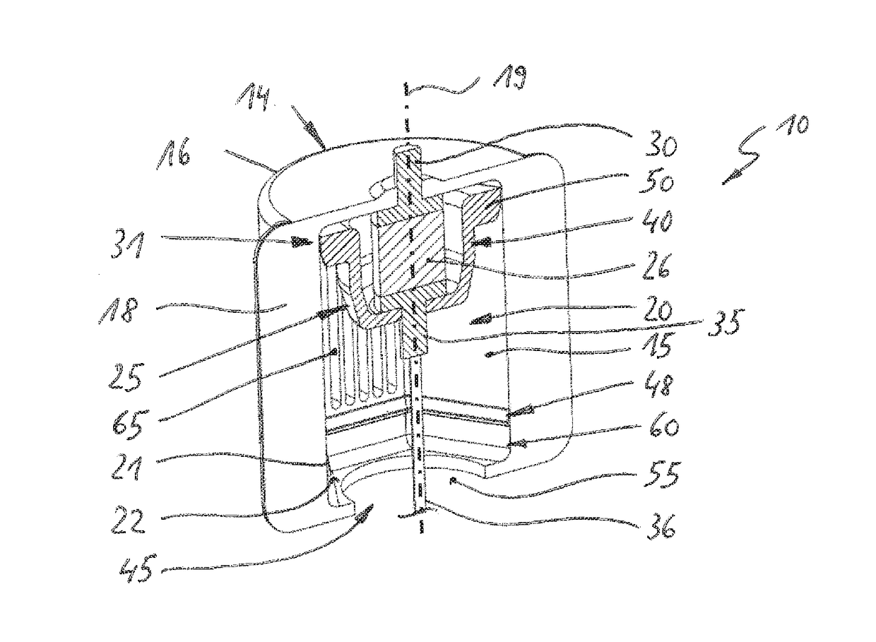
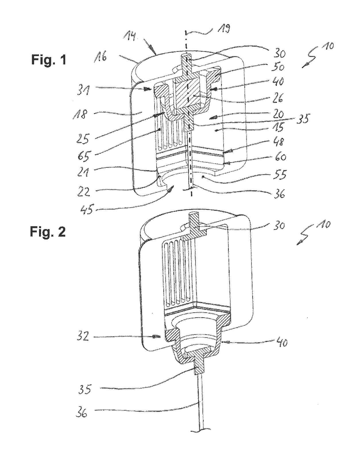
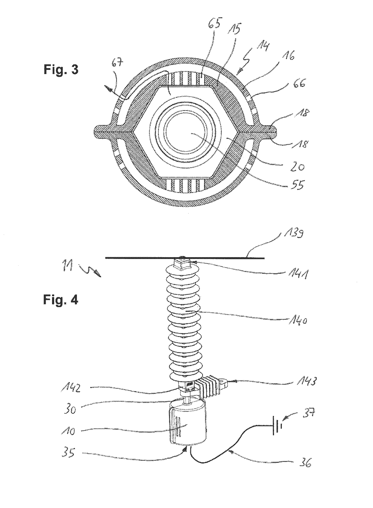
[0051]FIG. 1 shows together with FIG. 3 a first embodiment of a disconnector device 10 for a surge arrester. The disconnector device 10 has a housing unit 14, comprising an inner housing 15 and an outer housing 16 that extends about the inner housing 15. A gap 17 is provided between the inner housing 15 and the outer housing 16. FIG. 1 shows just one halve of the housing unit 14. The halves of the housing unit 14 are connected to one another at a flange portion 18 by a bolt-nut connection, by fusion, riveting or other suitable connection means. The housing unit is made of an insulating material, such as a polymeric material.

[0052]The inner housing 15 delimits a cavity 20 where a disconnector unit 25 is provided. The disconnector unit 25 has a first terminal 30, which protrudes out of the housing unit 14. The first terminal 30 is designed to be fastened to a surge arrester (not shown). A second terminal 35 of the disconnector unit is connectable to ground potential 37, for example by...

Example

[0068]A second embodiment of a disconnector device 100 is shown and described with respect to FIG. 5 and FIG. 6. Said second embodiment of a disconnector device 100 has basically the same working principle as the one described with respect to FIGS. 1 and 2. Hence, only the differences of the second embodiment compared to the first embodiment shall be discussed hereinafter whereas identical or at least functionally identical elements are provided with the same reference characters. FIG. 5 shows the disconnector device 100 in its pristine state, i.e. before operation whereas FIG. 6 shows it in its state after operation.

[0069]Please note that in the second embodiment of the disconnector device, the display of the outer housing 16 is there and arranged in the same fashion as shown in FIG. 3 but is not displayed in FIGS. 5 and 6 to keep the figures as simple as possible.

[0070]In the second embodiment, the cavity 20 in the inner housing 15 as well as the movable member 41 have a circular ...


PUM


Abstract

This disclosure concerns a disconnector device for a surge arrester. The disconnector device comprises a housing encompassing a cavity and a disconnector unit provided inside the cavity. The disconnector device is connectable to the surge arrester and to ground potential. The housing forms an inner housing of a housing unit. The housing unit comprising an inner housing and an outer housing. The at least one ventilation opening of the inner housing is fluidly connected to the at least one further ventilation opening of the outer housing such that a labyrinth with a gas escape path for the gases from the operating disconnector cartridge is formed.

Description

[0001]Aspects of the present disclosure relate to a disconnector device for permanently disconnecting the current flow in a surge arrester in case of a temporary overvoltage in the electric line lasting longer than a few tenths of milliseconds, e.g. longer than 100 ms extending over a few cycles up to several seconds or more. More particularly, they relate to a disconnector device providing for fire hazard protection.TECHNICAL BACKGROUND[0002]Metal oxide surge arresters are electrical devices installed in electrical grids in order to protect other electrical apparatuses from the consequences arising of destructive over voltages. Such consequences may result in damages of the electrical system as well as of its components. The working principle is based on a strongly nonlinear characteristic of the resistivity of metal oxide resistors as a function of the applied voltage. This allows a surge arrester to limit the damaging effects of a lightning-effected over voltage by draining curre...

Claims


Application Information

Patent Timeline
IPC IPC(8): H01C7/12H01H85/44H01H37/76H01H39/00H01T1/14
CPCH01H85/44H01C7/12H01H9/14H01C7/126H01T1/14H01H37/76H01H39/002H01T4/00H01T4/04H01T4/08H01H9/30
Inventor BOESE, RONALDGARIBOLDI, NICOLAMUGWYLER, REMOANTELO, JOEL
Owner HITACHI ENERGY SWITZERLAND AG
Why Eureka
Try Eureka