
Method for generating a speed signal of an electric motor

Active Publication Date: 2018-03-29
SCHAEFFLER TECH AG & CO KG
View PDF0 Cites 1 Cited by
  • Summary
  • Abstract
  • Description
  • Claims
  • Application Information

AI Technical Summary

Benefits of technology

The present invention provides a method to generate a speed signal for an electric motor that corrects for signal disturbances to better reflect the motor's actual speed. This method achieves a good correction of the speed signal by eliminating the distortion's waviness and filtering out the noise component. Additionally, the speed-dependent averaging does not require a full period of the disturbance signal.

Problems solved by technology

The noise component of the angle signal of the commutation sensor occurs due to disturbances in signal transmission.
The angle error is angle-dependent and consequently occurs periodically.
The angle signal measured by such a commutation sensor necessarily has disturbance components in the form of a noise component and an angle error.
Consequently, the angle error is periodic.

Method used


Image

  • Method for generating a speed signal of an electric motor
  • Method for generating a speed signal of an electric motor
  • Method for generating a speed signal of an electric motor

Examples


Embodiment Construction

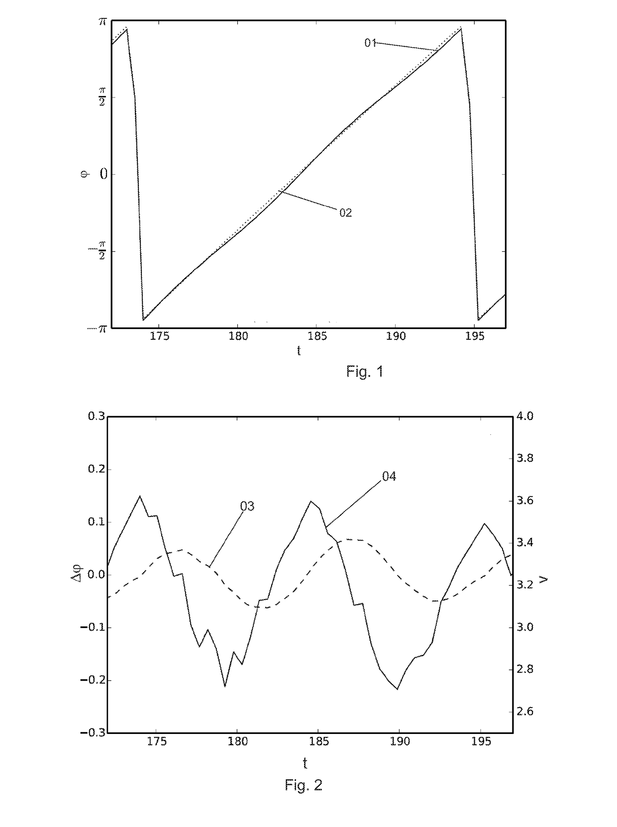
[0032]FIG. 1 shows the curve of an angle signal 01, measured by the commutation sensor, which shows the magnetic field angle as a function of time and shown as a continuous line. In contrast, ideal angle signal 02 is shown as a dashed line. For each rotation from −π to +π, angle signal 01 scans a full period. The comparison of ideal angle signal curve 02 with measured angle signal curve 01 shows that the commutation sensor records a slight angle error 03 which oscillates around ideal signal curve 02 on the angle signal similar to a sinusoidal disturbance signal.

[0033]FIG. 2 shows this angle error 03 as a magnetic field angle difference as a function of time, as well as raw speed signal 04, which is obtained by differentiating angle signal 01. It is apparent here that the waviness apparent in the curve of angle error 03 becomes more visible in raw speed signal 04 due to the differentiation, so that the error has a more distinct effect.

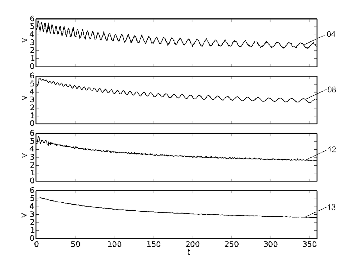
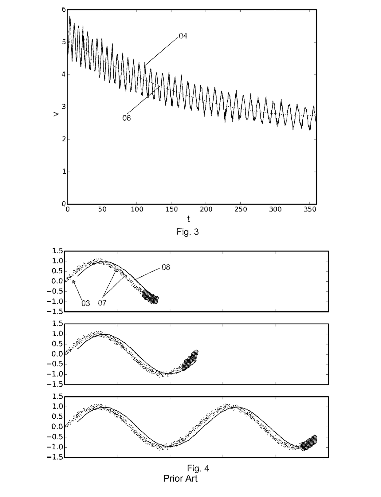
[0034]FIG. 3 shows how strong the amplification e...


PUM


Abstract

A method for the improved speed determination of electric motors while taking into account angle errors of an angular position sensor is provided. A commutation sensor based on a magnetic rotary encoder, the angle signal of which has an angle-dependent and thus periodic angle error, is used. By differentiation, this defective angle signal is converted into a raw speed signal, which has two disturbance components. One disturbance component results from the angle error and is the disturbance waviness, which is periodic similar to the angle error. The second disturbance component is formed by a noise component superposing the raw speed signal. In order to correct the defective raw speed signal, half of the period duration of the raw speed signal must be ascertained. If this half of the period duration is ascertained two samples of the raw speed signal lying exactly one half of the period duration of the raw speed signal apart from each other are averaged. A speed signal having no disturbance waviness but rather only the noise component results from these method steps.

Description

[0001]The present invention relates to a method for generating a speed signal, which is suitable for the improved speed determination of a rotatory electric motor. The improvement in the extraction of a signal representing the speed of the electric motor is achieved by taking into account the application-specific error form. In this case, a speed signal ascertained by a commutation sensor is corrected by a sample average. The speed of the electric motor may be an angular speed or a rotational speed. The present invention also relates to an electric motor system in which the above-named method is used.BACKGROUND[0002]An accurate speed signal is required wherever electric motors are used for a drive whose regulation is to be carried out more precisely than using a conventional block commutation. The speed signal may be ascertained using an angle signal, which may be detected by a commutation sensor. However, the angle signal and thus also the speed signal may have disturbances which p...

Claims


Application Information

Patent Timeline
IPC IPC(8): G01P3/487
CPCG01P3/487G01P3/48G01P3/489
Inventor KAUFNER, BENJAMIN
Owner SCHAEFFLER TECH AG & CO KG
Learn More