Method for detecting the vibrations of a roll stand

a technology of rolling stand and vibration, which is applied in the direction of manufacturing tools, measuring devices, and shaping safety devices, etc., can solve the problems of mass vibration, irregular thickness of the strip or breakage of the strip, and marks on the roll, etc., to make the effect of disturbing

Active Publication Date: 2007-03-13
CLECIM SAS
View PDF8 Cites 7 Cited by
  • Summary
  • Abstract
  • Description
  • Claims
  • Application Information

AI Technical Summary

Benefits of technology

[0018]For it has been observed by the inventors that the signal of the position sensor is disturbed by vibration, by an unexpected effect of transmission of that vibration through the entire stack of rolls constituting the roll stand and the hydraulic adjusting jack. Numerous supplementary tests have established that the position signal is completely modulated by the vibration in a manner which is entirely reliable and faithful in terms of frequency and amplitude. Modulation appears as of the start of the occurrence of vibration and the amplitude varies in accordance with that of the vibration, being superimposed on the amplitude variations of the signal which are caused by the action of the system for regulating the thickness.
[0019]It is therefore possible to provide a method for detecting the vibrations of a roll stand equipped with a hydraulic adjusting device by observing the measurement signal of the position sensor of the hydraulic adjusting jack; this digital position signal is clear of any background noise, it is normally observed by means of a sampling operation, the period of which is of the order of a millisecond, and it is necessary only to observe directly its amplitude variations over a given interval of time. It is not necessary to have a filter which would cause a delay of several periods relative to that of the vibration to be detected. In a method according to the invention, the measurement signal (POS) of the position sensor is memorized in real time and permanently, a sample of that signal is compared directly with a spatio-temporal observation window (F), of which the dimensions as well as the size of the sample are selected as a function of the roll stand and of the frequency of the vibrations to be detected, and a vibration detection signal is triggered when the signal sample is no longer contained within the window (F).

Problems solved by technology

These masses may inadvertently start to vibrate, in particular when high-speed rolling is attempted.
It can cause irregularities in the thickness of the strip or breakages of the strip, or marks on the rolls.
It is all the more disturbing to production since the most immediate remedy which can be applied to it is to reduce the rolling speed.
Moreover, the effects of those two types of vibration do not seem to be the same since it has been demonstrated that the vibrations of the third octave cause thickness defects and strip breakage while the vibrations of the fifth octave produce marks on the backing rolls.
However, the sensor, of the acceleration meter type, is very sensitive to all acceleration and the signal is generally spoilt by background noise.
However, this processing of the signal, in order to eliminate the background noise, generates a delay which may impair the triggering of the alarm and the corrective action at the desired moment.
Furthermore, simple processing in a frequency band does not enable the frequencies of vibrations that have a harmful origin to be distinguished from those that correspond to the normal vibrations caused by some rotating masses of the installation.
The problem of the location of the sensor and its fragility is thus solved but the problem of the processing of the signal remains because a microphone detects all of the acoustic frequencies present and the signal is spoilt by major background noise.
That method has disadvantages because the time taken to process the signal is too long and it basically detects the divergence of the start of vibration of a stand of the mill.
It has recently been observed that non-divergent vibrations may occur and impair the thickness or the surface state of the rolled product.
The device proposed can detect only the acoustic frequencies emitted by the stands of the tandem mill as a whole and it is not directly capable of differentiating the stands from one another.

Method used


Image

  • Method for detecting the vibrations of a roll stand
  • Method for detecting the vibrations of a roll stand
  • Method for detecting the vibrations of a roll stand

Examples


Embodiment Construction

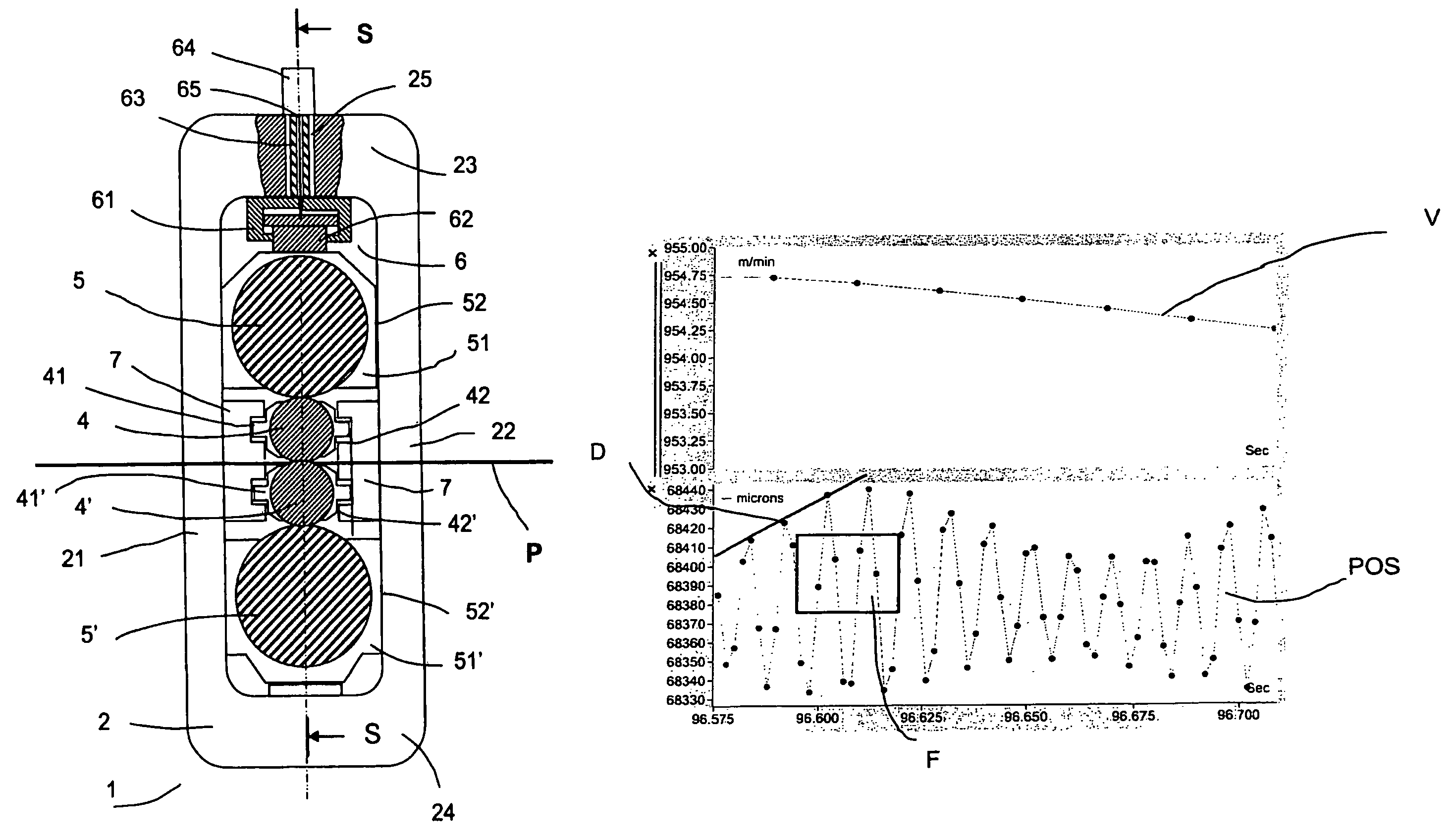
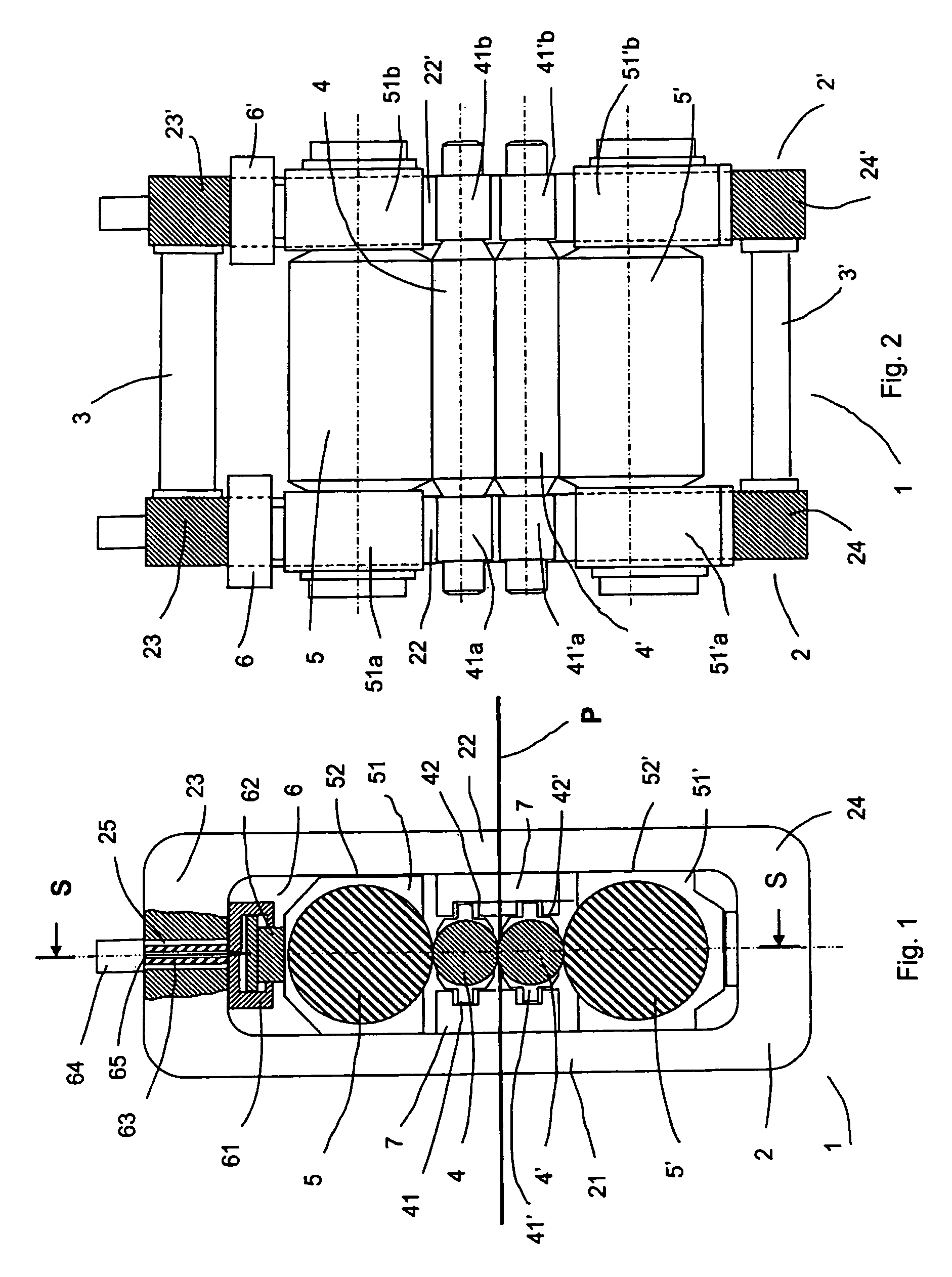
[0034]As shown in FIGS. 1 and 2, a roll stand 1 of the four-high type, which is known per se by the person skilled in the art, comprises two support columns 2 and 2′, respectively, spaced apart and connected by cross-members 3, 3′, between which is mounted a set of superposed rolls having parallel axes placed substantially in the same adjusting plane S perpendicular to the direction of displacement of the product P.

[0035]Each column 2, 2′ has a shape which is closed to form a ring and each comprises two upright pillars 21, 22 (21′, 22′, respectively) and two horizontal portions 23, 24 (23′, 24′, respectively).

[0036]The set of superposed rolls comprises two working rolls, 4, 4′ between which the product P passes, and two backing rolls 5, 5′ on which the working rolls rest.

[0037]It should be noted in passing that there are types of roll stand, other than four-high stands, which comprise more rolls, for example six-high stands, or fewer rolls, for example two-high stands. The invention...


PUM

PropertyMeasurementUnit
heightaaaaaaaaaa
frequenciesaaaaaaaaaa

Abstract

The invention relates to a method for detecting the vibrations of a roll stand (1) equipped with a hydraulic jack (6) as a device for adjusting the rolling rolls (4, 5). The hydraulic jack comprises a sensor (64) for measuring the position of the mobile portion relative to the fixed portion, this sensor supplying a digital signal (POS). In the method of the invention, the vibrations are detected by direct observation of the position signal (POS) and a comparison thereof relative to a spatio-temporal window (F) whose dimensions are determined as a function of the frequency to be detected. In accordance with the invention, it is possible to define different observation windows (F) suitable for the detection of different vibratory phenomena. In a tandem mill, the position signal (POS) of the hydraulic jack (6) of each roll stand (1) is observed in accordance with the method of the invention, which enables the commencement of vibration on each of the stands to be detected and the stand on which the phenomenon started to be determined.

Description

TECHNICAL FIELD[0001]The present invention relates to a method for detecting the vibrations of a roll stand, both in hot rolling and cold rolling, for various materials. The invention is particularly applicable to the detection of vibrations affecting thickness during the rolling of flat products in the form of strips, in particular using tandem mills.BACKGROUND OF THE INVENTION[0002]Metallurgical products, in particular flat products, such as sheet metal, strips or ribbons, irrespective of whether they are produced from steel, aluminium or other metals or alloys, are generally manufactured by rolling using mills formed by at least one roll stand and, for example, mills which are formed by a set of stands arranged in series to form what is known as a tandem mill train.[0003]In general, a roll stand comprises large rotating masses, such as working rolls and backing rolls, and reducing gears. These masses may inadvertently start to vibrate, in particular when high-speed rolling is att...

Claims


Application Information

Patent Timeline
Patent Type & Authority Patents(United States)
IPC IPC(8): B21B37/00B21B33/00B21B38/00
CPCB21B38/008B21B37/007B21B37/62B21B38/00
Inventor KARAM, MICHEL ABISABIO, EMILIO LOPEZ
Owner CLECIM SAS
Why Eureka
Try Eureka