Systems and methods for detection and demodulation of optical communication signals

a technology of optical communication signals and detection methods, applied in the direction of electromagnetic transmission, electrical equipment, close-range type systems, etc., to achieve the effect of soft steering and selective directionality

Active Publication Date: 2018-03-29
RAYTHEON CO
View PDF4 Cites 40 Cited by
  • Summary
  • Abstract
  • Description
  • Claims
  • Application Information

AI Technical Summary

Benefits of technology

[0003]Aspects and embodiments are directed to optical signal receivers formed from an array of detection elements, i.e., detectors, in combination with adaptive delays that combine the signals from the detectors such that constructive and destructive interference across the individual detectors results in effective wavefront correction. Additional benefits of a delay-combined array is that it may achieve selective directionality with adjustment of the adaptive delays to achieve soft steerability, not requiring mechanical alignment or re-positioning, and may operate without optics or lens systems to direct the light, and may operate with direct reception of the light in free space, e.g., without waveguides or focusing. Optical signal receivers in accord with aspects and embodiments disclosed herein may compensate for aberrations in the received light by operation of the detection elements, by adjusting delays applied to one or more of the detection elements, or a combination of these.

Problems solved by technology

Aspects and embodiments are directed to optical signal receivers formed from an array of detection elements, i.e., detectors, in combination with adaptive delays that combine the signals from the detectors such that constructive and destructive interference across the individual detectors results in effective wavefront correction.
Further, the signals from each of the detection elements of the array may be recorded and later combined with varying delays, allowing future recovery of any of multiple light signals after the fact.

Method used


Image

  • Systems and methods for detection and demodulation of optical communication signals
  • Systems and methods for detection and demodulation of optical communication signals
  • Systems and methods for detection and demodulation of optical communication signals

Examples


Embodiment Construction

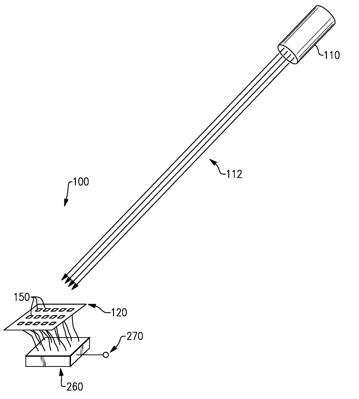
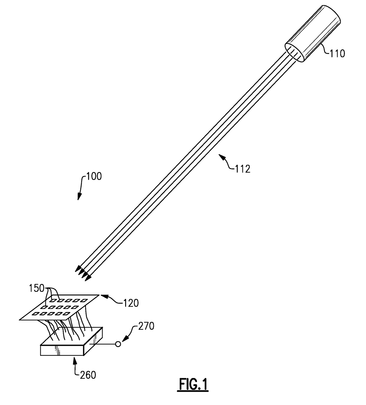
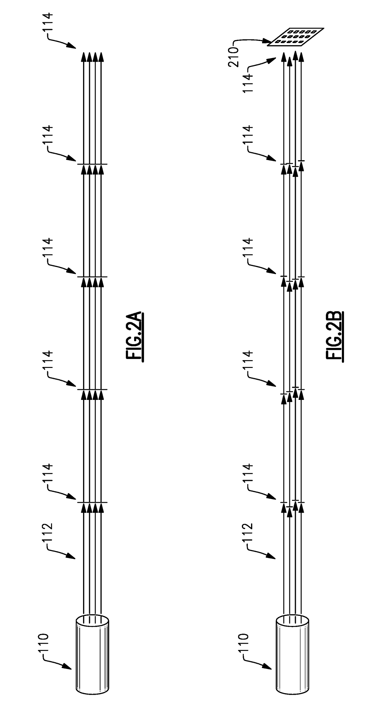
[0031]Aspects and embodiments are directed to arrays of detection elements as receivers for line-of-sight optical communications. The use of an array may allow light collection across an area of nondescript shape and size, and the number and placement of the detection elements may improve the signal-to-noise ratio in the received optical signal.

[0032]As discussed above, it may be desirable to maintain (or recover) coherency of the received optical signal, or to compensate for lack of coherency, particularly in applications where the optical signal may include phase modulation. Atmospheric perturbations tend to erode and ultimately destroy the coherency of an optical signal. Conventional approaches of adaptive optics to compensate for wavefront variation caused by air perturbations have several disadvantages, including large size and weight. Further, precise alignment of all elements of an adaptive optics system and precise control of the adaptive optics is generally required for acc...


PUM


Abstract

A free-space optical signal receiver includes a plurality of detectors whose individual outputs are delayed to correct for variations in arrival time caused by aberration in the medium through which the optical signal propagates, and combined to provide a single output. Each of the plurality of detectors sense the free-space modulated optical signal and provide a detector signal representative of the modulation of the optical signal. Each detector signal is delayed by a delay value to generate a delayed signal, and each delay value is selected to correct for variation in arrival time of the optical signal at each of the detectors, resulting in the delayed signals being substantially time-aligned. The delayed signals are constructively combined into a combined signal representative of the modulation aspect, and the combined signal is provided as an output.

Description

BACKGROUND[0001]Light waves may be made to carry information by modulating a light source, often a laser source, to change various properties of the light, such as its amplitude, phase, frequency, wavelength, etc. The light waves may be in the visible spectral band, the infrared spectral band, or another region of the electromagnetic spectrum. In some cases, an underlying signal, such as a radio frequency signal, may be modulated via amplitude, phase, or frequency modulation, or any combination thereof, and the light source may be modulated by the underlying signal. Optical receivers receive the light waves and measure properties or variations of the light wave, such as the amplitude, phase transitions, and the like, from which the underlying signal and the information may be recovered.[0002]A receiver for line-of-sight communications using modulated light waves, such as a modulated laser beam, should collect signal from a large enough area that the acquired signal power is high eno...

Claims


Application Information

Patent Timeline
Patent Type & Authority Applications(United States)
IPC IPC(8): H04B10/69H04B10/11H04B10/516
CPCH04B10/697H04B10/516H04B10/11H04B10/114H04B10/671
Inventor DOLGIN, BENJAMIN P.GRACEFFO, GARY M.KOWALEVICZ, ANDREW
Owner RAYTHEON CO
Why Eureka
Try Eureka