Wound dovetail wedge for marine propeller retention

a wedge and propeller technology, applied in the field of marine propellers, can solve the problems of bending or damaging the blade, requiring replacement of the entire assembly of the blade, and even one blade being damaged,

Inactive Publication Date: 2018-04-19
GENERAL ELECTRIC CO
View PDF12 Cites 6 Cited by
  • Summary
  • Abstract
  • Description
  • Claims
  • Application Information

AI Technical Summary

Problems solved by technology

Disadvantages include that if the blade struck a foreign object, enormous forces could be transmitted through the metal blade and hub to the drive shaft, possibly bending it or damaging its mounting.
Also the blades are heavy.
Damage to even one blade required replacement of the entire assembly because the blades and hub formed a single piece.

Method used


Image

  • Wound dovetail wedge for marine propeller retention
  • Wound dovetail wedge for marine propeller retention
  • Wound dovetail wedge for marine propeller retention

Examples


Embodiment Construction

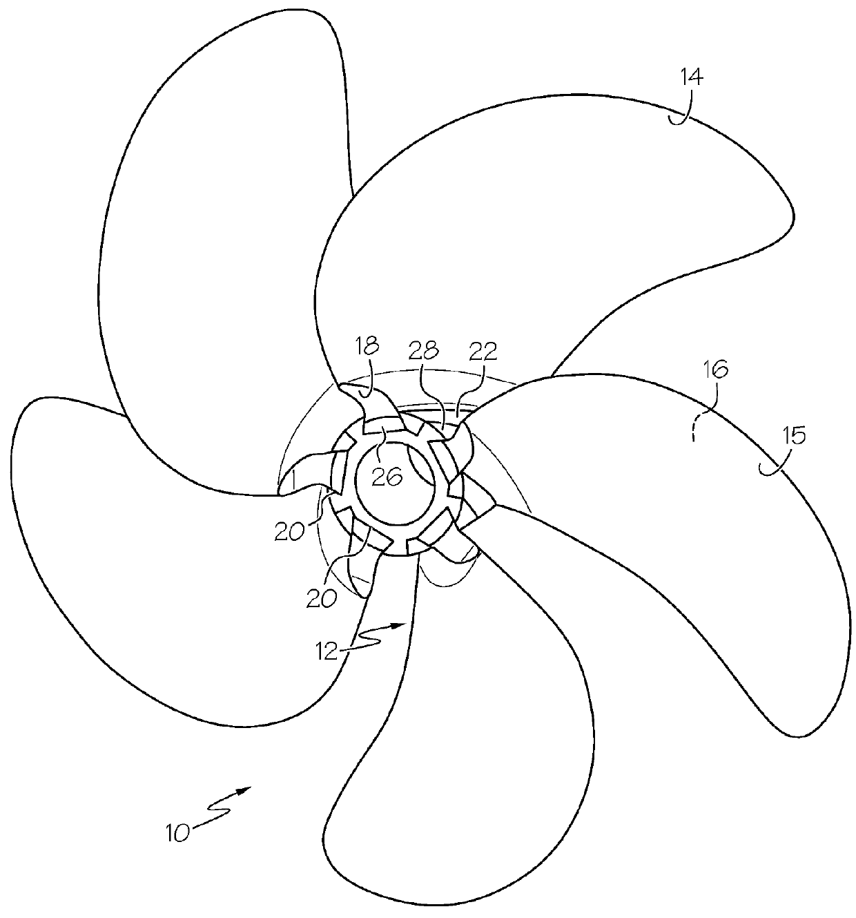
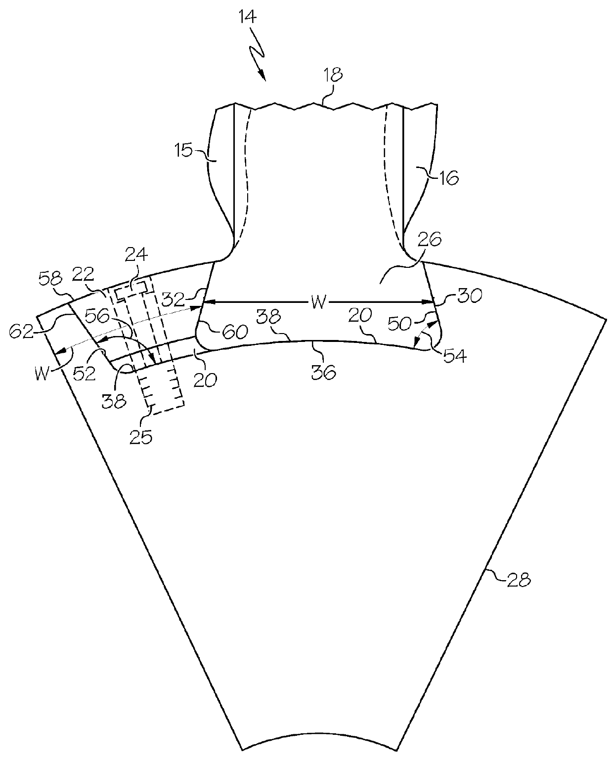
[0016]Illustrated schematically in FIG. 1 is a marine propeller 10 including a metallic hub and blade assembly 12. The exemplary embodiment of the assembly 12 illustrated herein has composite blades 14 with axially extending composite blade roots 18 mounted in axially extending hub slots 20 in a metallic hub 28 and secured therein with axially extending wedges 22. The exemplary embodiment of the blade root 18 includes a dovetail 26 which is secured in a hub slot 20 in the hub 28 by a radially inserted and secured dovetail wedge 22.

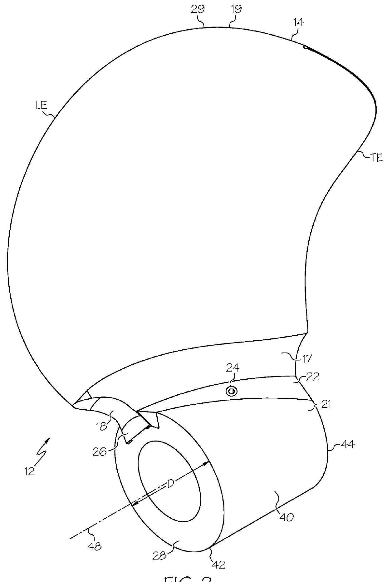
[0017]Referring to FIGS. 1 and 2, each of the composite blades 14 includes a blade back or suction or forward side 15 of the blade 14 (surface facing the bow) extending from the blade root 18 out to a blade tip 29. A blade face is referred to as a pressure, pitch, or aft side 16 of the blade 14 (surface facing the stern). The blade root 18 include a fillet 17 which is a region of transition from the blade surfaces, the forward and aft sides 15 and 16, and ...


PUM


Abstract

A marine propeller composite blade an axially extending composite blade root including a dovetail wound in a partial spiral or helix around a centerline. Dovetail tapering down in width between clockwise and counter-clockwise dovetail sides of dovetail from dovetail bottom in a radially outwardly direction away from centerline. Marine propeller may include composite blade roots mounted in axially extending hub slots in a metallic hub, axially extending wedges disposed within the hub slots circumferentially between the blade roots and one of clockwise slot sides and counter-clockwise slot sides, and the wedges abutting the blade roots and the one of clockwise slot sides and counter-clockwise slot sides. Wedges and hub slots wound in a partial spiral or helix around a centerline. Radial retention means for radially retaining wedges in hub slots may include bolts engaging wedges and screwed into threaded holes in hub.

Description

BACKGROUND OF THE INVENTIONTechnical Field[0001]The present invention relates generally to marine propellers and, specifically, relates to a metallic hub and blade assembly with composite blades.Background Information[0002]Marine propellers have traditionally been cast or forged of metal and the hub and blades were formed as a single unitary part. This design provided strength and reliability that the blades would not come loose from the hub. Disadvantages include that if the blade struck a foreign object, enormous forces could be transmitted through the metal blade and hub to the drive shaft, possibly bending it or damaging its mounting. Also the blades are heavy. Damage to even one blade required replacement of the entire assembly because the blades and hub formed a single piece.[0003]Molded plastic propellers were developed. U.S. Pat. No. 4,930,987 discloses marine propeller blades including, at their roots, a root portion that slides axially into a re-entrant cavity that extends...

Claims


Application Information

Patent Timeline
Patent Type & Authority Applications(United States)
IPC IPC(8): B63H1/20B63H1/26
CPCB63H1/20B63B2748/00B63H1/26
Inventor KRAY, NICHOLAS JOSEPHBAEHMAN, PEGGY LYNNVAN NIEUWENHOVE, STEFAAN GUIDO
Owner GENERAL ELECTRIC CO
Why Eureka
Try Eureka