Electric wire with terminal and manufacturing method of electric wire with terminal

Active Publication Date: 2018-04-19
YAZAKI CORP
View PDF16 Cites 3 Cited by
  • Summary
  • Abstract
  • Description
  • Claims
  • Application Information

AI Technical Summary

Benefits of technology

The invention is about an electric wire with a terminal that can maintain good performance. The patent describes a method for making this type of wire and a machine used to crimp the terminal onto the wire. The goal is to improve the quality and reliability of electric wires with terminals.

Problems solved by technology

In the crimping terminal including the water stop member, in a case where the protruding water stop member is attached to a metal mold, the sealing properties easily decrease.

Method used


Image

  • Electric wire with terminal and manufacturing method of electric wire with terminal
  • Electric wire with terminal and manufacturing method of electric wire with terminal
  • Electric wire with terminal and manufacturing method of electric wire with terminal

Examples


embodiments

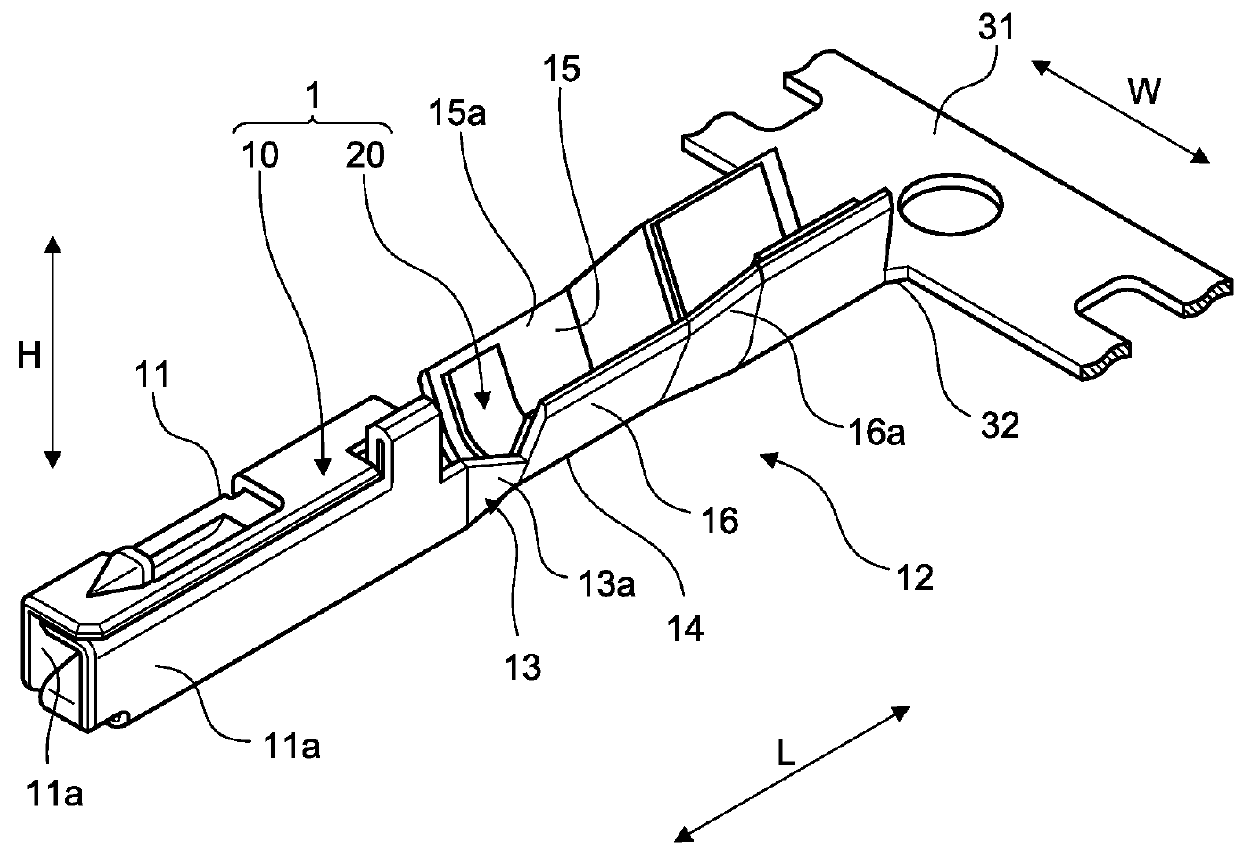
[0042]Embodiments will be described with reference to FIG. 1 to FIG. 21. This embodiment relates to an electric wire with a terminal, a manufacturing method of an electric wire with a terminal, and a terminal crimping apparatus. Furthermore, FIG. 13 illustrates a sectional surface taken along line XIII-XIII of FIG. 9. FIG. 15 illustrates a sectional surface taken along line XV-XV of FIG. 14. FIG. 18 illustrates a sectional surface taken along line XVIII-XVIII of FIG. 17.

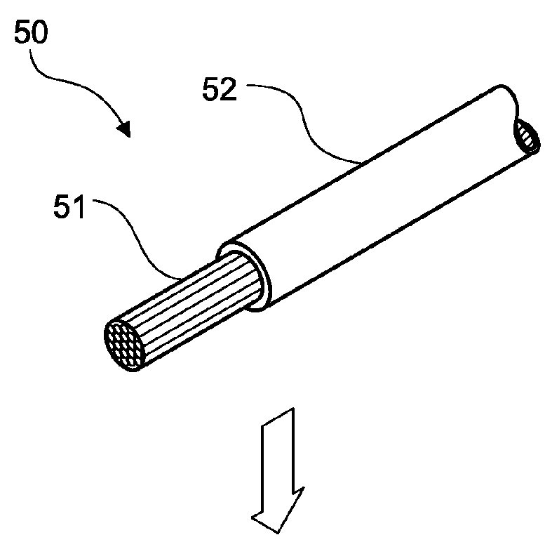
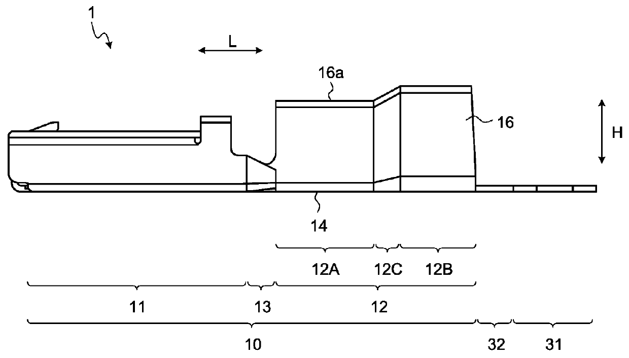
[0043]First, a crimping terminal 1 according to this embodiment will be described. The crimping terminal 1 illustrated in FIG. 1 or the like is a terminal crimped with respect to an electric wire 50. The crimping terminal 1 is electrically connected to a counterpart terminal (not illustrated) in a state of being integrated with the electric wire 50. In the electric wire 50 which is a crimping target, a cover 52 in an end portion is removed, and thus, a core 51 is exposed by a predetermined length. The core 51 may be ...

first modification example of embodiment

[0139]A first modification example of the embodiment will be described. FIG. 29 is a front view of a second metal mold according to the first modification example of the embodiment, FIG. 30 is a sectional view of the second metal mold according to the first modification example of the embodiment, and FIG. 31 is a diagram illustrating an operation at the time of crimping. FIG. 30 illustrates a sectional surface taken along line XXX-XXX of FIG. 29. In a second metal mold 113 of the first modification example, a difference from the second metal mold 113 of the embodiment described above is that the shape of the front end of the first wall surface 115 and the second wall surface 116 is curved. The second metal mold 113 according to the first modification example suppresses the occurrence of chipping of the joining portion 13.

[0140]As illustrated in FIG. 29 and FIG. 30, each of curved portions 115a and 116a is disposed on the front end of the first wall surface 115 and the second wall su...

second modification example of embodiment

[0143]A second modification example of the embodiment will be described. The water stop member 20 may not protrude from the electric wire connection portion 12 after being crimped. The water stop member 20 may not protrude from the electric wire connection portion 12 insofar as the water stop member 20 covers the tip end of the core 51, and suitably seals a gap between the core 51 and the electric wire connection portion 12.

[0144]The shape of the diameter expansion portion 113C is not limited to the exemplified shape. For example, the diameter expansion portion 113C may be formed such that the sectional area of the space surrounded by the concave portion 113A1 and the first metal mold 112 gradually increases as being directed towards the tip end side of the core 51. In contrast, the diameter expansion portion 113C may be formed such that the sectional area of the space surrounded by the concave portion 113A1 and the first metal mold 112 gradually decreases as being directed towards ...


PUM


Abstract

An electric wire with a terminal includes an electric wire, and a crimping terminal including an electric wire connection portion crimped by being wound around a core and a cover of the electric wire, a diameter expansion portion which contains a water stop member covering a tip end portion of the core and sealing a gap between the core and the electric wire connection portion is provided in an end portion of the electric wire connection portion on a tip end side of the core, and a sectional area of the diameter expansion portion is greater than a sectional area at a portion on the base end side of the core with respect to the diameter expansion portion.

Description

CROSS-REFERENCE TO RELATED APPLICATION(S)[0001]The present application claims priority to and incorporates by reference the entire contents of Japanese Patent Application No. 2016-201871 filed in Japan on Oct. 13, 2016 and Japanese Patent Application No. 2017-135454 filed in Japan on Jul. 11, 2017.BACKGROUND OF THE INVENTION1. Field of the Invention[0002]The present invention relates to an electric wire with terminal, a manufacturing method of an electric wire with a terminal, and a terminal crimping apparatus.2. Description of the Related Art[0003]In the related art, there are a crimping terminal crimped with respect to a core of an electric wire, and a terminal crimping apparatus crimping the crimping terminal with respect to the electric wire. As an example of the crimping terminals, in WO 2011 / 122622 A, a technology of a crimping terminal including a barrel piece configuring a crimping unit crimping an exposed portion of an electric wire conductor, exposed with a predetermined l...

Claims


Application Information

Patent Timeline
IPC IPC(8): H01R4/18H01R4/62H01R4/70H01R43/00H01R43/058H01R43/055
CPCH01R4/18H01R4/184H01R4/62H01R4/70H01R43/005H01R43/058H01R43/055H01R13/52H01R43/0488H01R43/048H01R4/185H01R13/5216
Inventor SAITO, HIDEKIIWASAWA, HIDEHIKOTAKAYANAGI, MASAYOSHISATO, KEISHINOHARA, JUNYA
Owner YAZAKI CORP
Why Eureka
Try Eureka