Lithium secondary battery and method of manufacturing the same

a secondary battery and lithium battery technology, applied in sustainable manufacturing/processing, non-aqueous electrolyte cells, cell components, etc., can solve the problems of 372 mab, obstacle to achieving a higher battery capacity, and the upper limit of battery capacity is limited, so as to promote particle fracture, high reaction uniformity, and large strain

Active Publication Date: 2009-12-10
PANASONIC ENERGY CO LTD
View PDF20 Cites 75 Cited by
  • Summary
  • Abstract
  • Description
  • Claims
  • Application Information

AI Technical Summary

Benefits of technology

[0017]In the silicon/silicon alloy particles of the present invention that have a crystallite size of 100 nm or less, a large number of crystallites exist in a particle because the crystallite size is small relative to the particle size. Therefore, the lithium tends to move easily into the active material particle during charge and discharge because of grain boundary diffusion of lithium, so the reaction uniformity in the particle is very high. When the reaction uniformity in the particle is low, a large strain occurs in the particle due to an increase in difference of the amounts of volumetric changes in the particle. Consequently, fractures of the particle are promoted. However, when the above-described restriction is made, the reaction uniformity becomes very high. Therefore, such fractures in the particles are prevented, and very good charge-discharge characteristics can be obtained.
[0018]In addition, when the silicon/silicon alloy particles have a crystallite size of 100 nm or less, there are a large number of crystallites in a particle, so the silicon/silicon alloy particles have very small surface irregularities. When the surfaces of the silicon/silicon alloy particles have such small irregularities, the negative electrode binder gets into such irregular portions, exerting an anchoring effect. Therefore, an advantageous effect is achieved that the adhesion of the silicon/silicon alloy particles with one another improves further.
[0...

Problems solved by technology

When using a negative electrode material composed of graphite, lithium occlusion is only possible up to the composition LiC6, and the upper limit of battery capacity is limited to the theoretical capacity 372 mAb/g.
This has been an obstacle to achieving a higher battery capacity.
When silicon is used as the negative electrode active material, however, the negative electrode active material undergoes expansion and shrinka...

Method used


Image

  • Lithium secondary battery and method of manufacturing the same
  • Lithium secondary battery and method of manufacturing the same
  • Lithium secondary battery and method of manufacturing the same

Examples


example 4

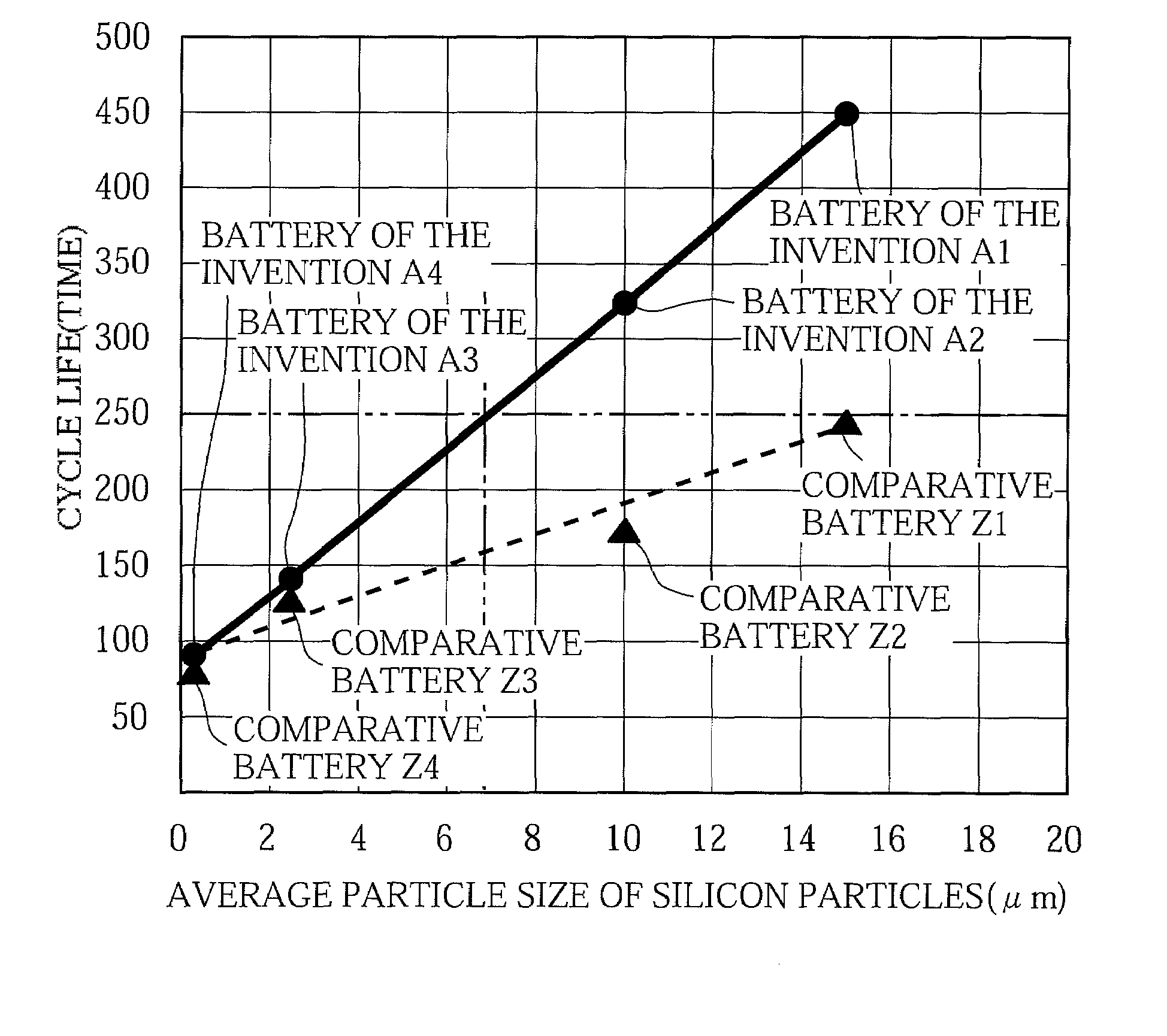
[0107]A battery was fabricated in the same manner as described in Example 1 above, except that the polycrystalline silicon particles used had a crystallite size of 58 nm, an average particle size of 0.3 μm, and a particle size distribution in which D10 was 0.1 μm, D50 was 0.3 μm and D90 was 0.9 μm.

[0108]The battery fabricated in this manner is hereinafter referred to as Battery A4 of the invention.

experiment 3

(Experiment 3)

[0132]The physical properties (imidization ratio and glass transition temperature) of the binder resin A were measured.

[0133]For the measurement, the precursor of the polyimide resin A, polyamic acid varnish, alone was dried in the air at 120° C., as in the conditions for preparing the negative electrode, and was thereafter heat-treated under an argon atmosphere at 400° C. for 10 hours, to thereby prepare a block of binder resin A.

[0134]The imidization ratio was determined by IR spectroscopy, and it was found that no peak due to acid amide sites was observed with the block of the heat-treated binder resin A and that the imidization ratio was 100%.

[0135]The glass transition temperature as determined by a DSC (differential scanning calorimetry) measurement was 285° C.

Second Group of Examples

[0136]In the Second Group of Examples, a study was conducted about how the positive / negative electrode theoretical electrical capacity ratio affects the battery performance.

Example 1

[...

examples 2 to 10

[0157]Batteries were fabricated in the same manner as described in Example 1 above, except that the average particle sizes and the amounts (mass ratios relative to the negative electrode active material particles) of the graphite powders added were as set forth in Table 4 blow.

[0158]The batteries fabricated in these manners are hereinafter referred to as Batteries D2 to D10 of the invention, respectively.

(Experiment)

[0159]The just-mentioned Batteries D1 to D10 of the invention were charged and discharged under the same conditions as described in the foregoing experiment of the First Group of Examples, to determine the cycle life for each battery. The results are shown in Table 4 below. Table 4 also shows the cycle life of Battery A1 of the invention.

TABLE 4Negative electrode conductive agentAverage particleAmount addedCycle lifeBatterysize (μm)(mass %)(times)D113433D23.5502D35494D410489D515477D620441D73.51448D810463D920456D1025395A1——450

[0160]The results shown in Table 4 clearly dem...


PUM

PropertyMeasurementUnit
Temperatureaaaaaaaaaa
Percent by massaaaaaaaaaa

Abstract

[Problem] An object of the invention is to provide a lithium secondary battery that shows good cycle performance and at the same time prevents a battery thickness increase due to charge-discharge cycles, and a method of manufacturing such a battery.
[Means for Solving the Problem] A lithium secondary battery includes a negative electrode (2) having a negative electrode current collector (11) and a negative electrode active material layer (12) disposed on the negative electrode current collector (11), a positive electrode (1) having a positive electrode active material, a separator (3), and a non-aqueous electrolyte. The negative electrode active material layer includes negative electrode active material particles and a negative electrode binder, and the negative electrode active material particles include silicon particles and/or silicon alloy particles. The silicon particles and the silicon alloy particles have a crystallite size of 100 nm or less.

Description

TECHNICAL FIELD[0001]The present invention relates to lithium secondary batteries and methods of manufacturing the batteries.BACKGROUND ART[0002]Various mobile communication devices and mobile electronic devices such as laptop computers have emerged in recent years, and this has lead to a demand for higher capacity batteries as their driving power sources. Lithium secondary batteries, which perform charge-discharge operations by transferring lithium ions between the positive and negative electrodes, have been widely used as the driving power source for the mobile communication devices and the like since the lithium secondary batteries have higher energy density and higher capacity than other types of secondary batteries such as nickel-cadmium batteries. Nevertheless, as the mobile communication devices and other electronic devices have increasingly become smaller and lighter, there has been a demand for further improvements in the energy density and cycle performance of the lithium ...

Claims


Application Information

Patent Timeline
IPC IPC(8): H01M4/58H01M4/38H01M4/62H01M4/48H01M6/14H01M4/82H01M4/134H01M4/1395H01M4/587H01M10/052H01M10/0567H01M10/058H01M10/0587
CPCH01M4/134H01M10/0587Y10T29/49115Y02E60/122H01M2004/021Y02P70/50Y02E60/10H01M4/38H01M4/04H01M4/62H01M10/05
Inventor FUKUI, ATSUSHIMINAMI, HIROSHIKUSUMOTO, YASUYUKI
Owner PANASONIC ENERGY CO LTD
Why Eureka
Try Eureka