Protective film and composition for preparing the same, slurry, and electrical storage device

a technology of protective film and composition, which is applied in the manufacture of final products, electrode manufacturing processes, textiles and paper, etc., can solve the problems of short circuit, reduced size short circuit of electrical storage devices, etc., and achieve excellent electrolyte solution permeability/retention ability, excellent charge-discharge characteristics, and suppress the effect of internal resistance increas

Active Publication Date: 2014-09-18
ENEOS MATERIALS CORP
View PDF8 Cites 22 Cited by
  • Summary
  • Abstract
  • Description
  • Claims
  • Application Information

AI Technical Summary

Benefits of technology

[0028]An electrical storage device that includes a protective film formed using the protective film-forming composition according to one aspect of the invention exhibits excellent electrolyte solution permeability / retention capability, and can suppress an increase in internal resistance. Specifically, since the internal resistance of the electrical storage device increases to only a small extent even when subjected to repeated charge and discharge, or overcharge, the electrical storage device exhibits excellent charge-discharge characteristics. Since the protective film is provided between the cathode and the anode, it is possible to suppress occurrence of a short circuit that that may occur due to a dendrite produced during charge and discharge.
[0029]Since the protective film-forming composition according to one aspect of the invention exhibits excellent oxidation resistance, the protective film-forming composition may suitably be used to form a protective film that is situated opposite to the cathode of an electrical storage device.

Problems solved by technology

However, a short circuit may easily occur when the interval between the cathode and the anode decreases along with a reduction in size of the electrical storage device.
If a dendrite has been grown through the separator, and has reached the surface of the other electrode, the electrical storage device is short-circuited, and the charge / discharge function is lost.

Method used


Image

  • Protective film and composition for preparing the same, slurry, and electrical storage device
  • Protective film and composition for preparing the same, slurry, and electrical storage device
  • Protective film and composition for preparing the same, slurry, and electrical storage device

Examples


first embodiment

1.1. First Embodiment

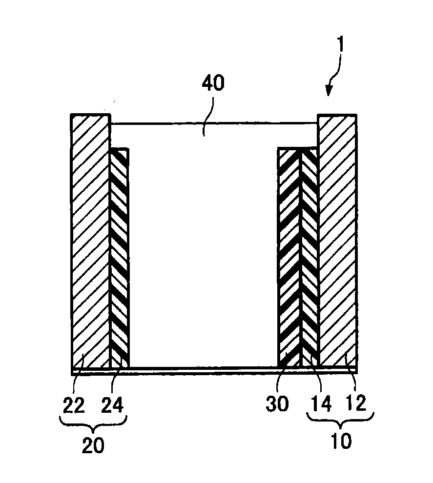
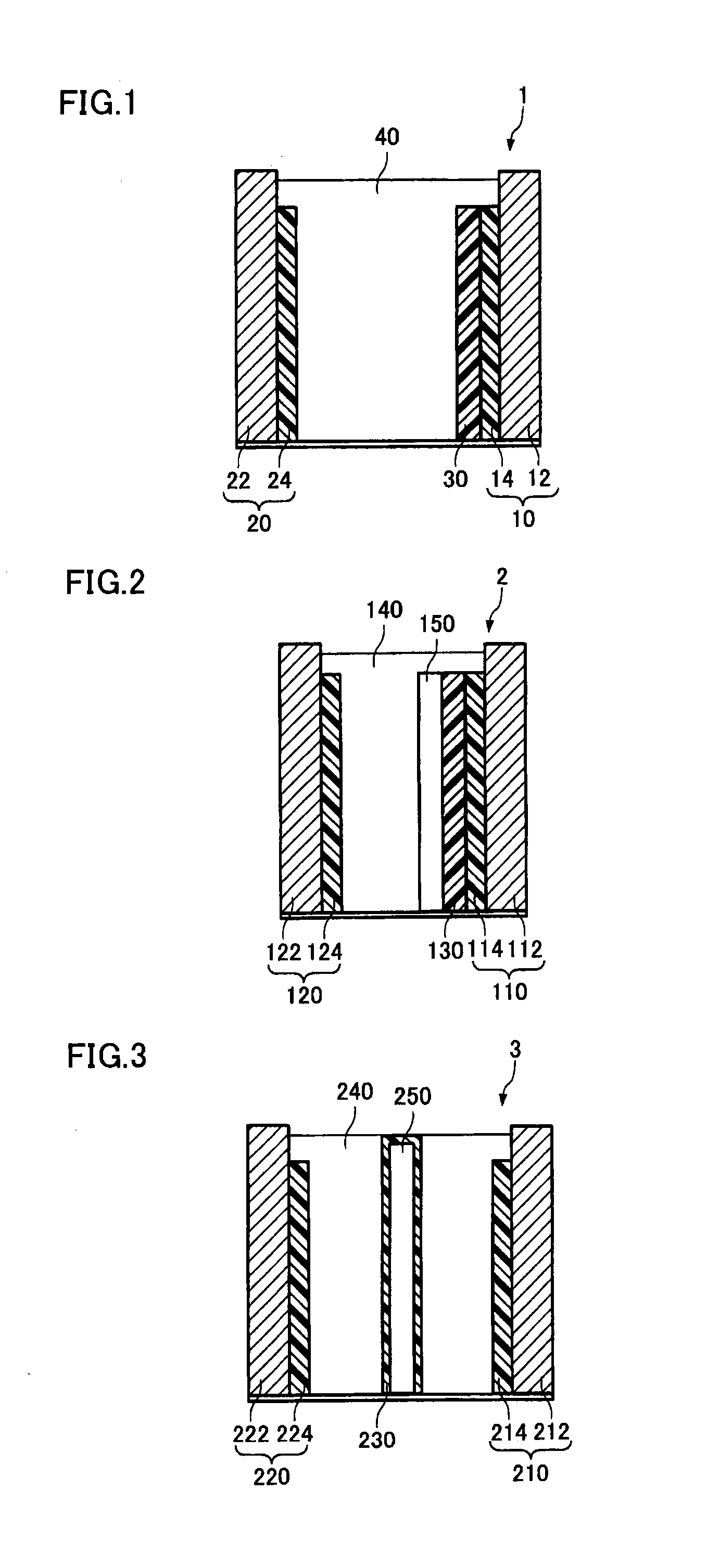
[0038]FIG. 1 is a schematic view illustrating the cross section of an electrical storage device according to the first embodiment. As illustrated in FIG. 1, an electrical storage device 1 includes a cathode 10 that is formed by forming a cathode active material layer 14 on the surface of a cathode current collector 12, an anode 20 that is formed by forming an anode active material layer 24 on the surface of an anode current collector 22, a protective film 30 that is provided between the cathode 10 and the anode 20, and an electrolyte solution 40 with which the space between the cathode 10 and the anode 20 is filled. In the electrical storage device 1, a separator is not provided between the cathode 10 and the anode 20. A situation in which the cathode 10 and the anode 20 come in contact with each other, and are short-circuited does not occur as long as the cathode 10 and the anode 20 are sufficiently secured by a solid electrolyte or the like.

[0039]Although the ...

second embodiment

1.2. Second Embodiment

[0055]FIG. 2 is a schematic view illustrating the cross section of an electrical storage device according to the second embodiment. As illustrated in FIG. 2, an electrical storage device 2 includes a cathode 110 that is formed by forming a cathode active material layer 114 on the surface of a cathode current collector 112, an anode 120 that is formed by forming an anode active material layer 124 on the surface of an anode current collector 122, a protective film 130 that is provided between the cathode 110 and the anode 120, an electrolyte solution 140 with which the space between the cathode 110 and the anode 120 is filled, and a separator 150 that is provided between the cathode 110 and the anode 120.

[0056]The electrical storage device 2 differs from the electrical storage device 1 in that the protective film 130 is provided so as to be held between the cathode 110 and the separator 150. Although the electrical storage device 2 illustrated in FIG. 2 has a con...

third embodiment

1.3. Third Embodiment

[0060]FIG. 3 is a schematic view illustrating the cross section of an electrical storage device according to the third embodiment. As illustrated in FIG. 3, an electrical storage device 3 includes a cathode 210 that is formed by forming a cathode active material layer 214 on the surface of a cathode current collector 212, an anode 220 that is formed by forming an anode active material layer 224 on the surface of an anode current collector 222, an electrolyte solution 240 with which the space between the cathode 210 and the anode 220 is filled, a separator 250 that is provided between the cathode 210 and the anode 220, and a protective film 230 that is provided to cover the surface of the separator 250.

[0061]The electrical storage device 3 differs from the electrical storage device 1 and the electrical storage device 2 in that the protective film 230 is provided to cover the surface of the separator 250. According to the above configuration, a short circuit does ...


PUM

PropertyMeasurementUnit
number average particle sizeaaaaaaaaaa
temperatureaaaaaaaaaa

Abstract

An electrical storage device includes a cathode, an anode, a protective film that is provided between the cathode and the anode, and an electrolyte solution, the protective film including a polymer that includes a repeating unit derived from a fluorine-containing monomer, and a repeating unit derived from an unsaturated carboxylic acid.

Description

TECHNICAL FIELD[0001]The present invention relates to a protective film that may be used for an electrical storage device, a composition for forming the protective film, a slurry, and an electrical storage device that includes the protective film.BACKGROUND ART[0002]In recent years, a high-voltage electrical storage device having high energy density has been desired as a power supply for driving an electronic device. In particular, a lithium-ion battery and a lithium-ion capacitor are expected to be a high-voltage electrical storage device having high energy density.[0003]A reduction in size has been desired for such a high-voltage electrical storage device having high energy density. In order to reduce the size of the electrical storage device, it is necessary to reduce the thickness of the separator that isolates the cathode and the anode in addition to the thickness of the cathode, the anode, and the like, for example. However, a short circuit may easily occur when the interval b...

Claims


Application Information

Patent Timeline
Patent Type & Authority Applications(United States)
IPC IPC(8): C08L27/16H01G11/00H01M2/16C08L33/08C08K3/22C08L33/12H01G9/145H01G9/07H01M50/414
CPCC08L27/16H01G9/145H01G11/00H01G9/07C08K2003/2241C08K3/22C08L33/12H01M2/1653H01M2/1673C08L33/08H01G11/52H01M4/04H01M10/052H01M50/414Y02E60/10Y02P70/50H01M50/446H01M50/451H01M50/443H01M50/434H01M50/426H01M50/42H01M50/449H01M50/46H01M50/431H01G9/02Y02E60/13
Inventor OTSUKA, YOSHIHARUKITAGUCHI, HIRONORIFUJIHARA, NOBUYUKI
Owner ENEOS MATERIALS CORP
Why Eureka
Try Eureka