High-voltage electric double layer capacitor

a double-layer capacitor, high-voltage technology, applied in the direction of electrolytic capacitors, capacitors, electrical equipment, etc., can solve the problems of increasing the number of unit cells, the balance problem between the unit cells, and the inability to apply high voltage to any one of the unit cells, so as to increase the number of electrodes, increase the surge voltage and operating voltage

Inactive Publication Date: 2006-10-05
KORCHIP CORP
View PDF4 Cites 24 Cited by
  • Summary
  • Abstract
  • Description
  • Claims
  • Application Information

AI Technical Summary

Benefits of technology

[0025] The present invention is characterized in that the number of electrodes within the unit cell is increased to increase the number of electrodes and facing surfaces of the electrodes. According to the present invention, the increased electrodes serve as bridges to serially connect the electrodes within the unit cell, thereby increasing a surge voltage and an operating voltage. Furthermore, even though a high voltage of 3.0V or more is applied to the unit cell, the voltage is distributed within the unit cell and thus an electrolyte is not dissolved. Accordingly, the unit cell has an increased surge voltage and operating voltage, a high energy storage density, and a superior charge / discharge characteristic. Furthermore, as the unit cell has a high operating voltage, the EDLC of the present invention can be fabricated as a single cell. If the EDLC is fabricated as a single cell, a manufacturing process can be simplified and the EDLC can be miniaturized.

Problems solved by technology

Therefore, there is a problem in that two or more unit cells have to be connected in series in order to establish an operating voltage applicable to electronic products.
However, in the case where two or more unit cells (each 3.0V or less) are serially connected to increase the operating voltage of a capacitor, there is another problem in that a balance problem between the unit cells, which inevitably occurs, should be solved.
This method has a problem in that a high voltage is applied to any one of the unit cells since voltage balance among the unit cells is broken due to repeated cycles in the capacitance of a unit cell, a capacitance change rate, an ESR, a resistance changing rate, a leakage current, and a leakage current change rate.

Method used


Image

  • High-voltage electric double layer capacitor
  • High-voltage electric double layer capacitor
  • High-voltage electric double layer capacitor

Examples


example 1

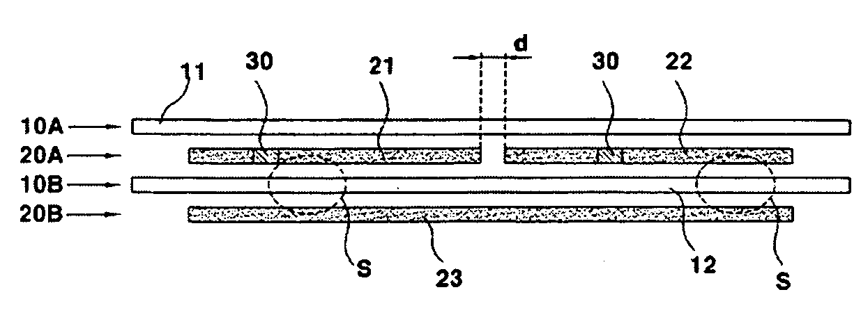
[0069] A terminal 30 was drawn from each of typical activated carbon electrodes for an EDLC, and the electrodes were arbitrarily divided into a positive electrode 21 and a negative electrode 22. The two electrodes 21 and 22 were arranged parallel to each other. An additional bridge electrode 23 was then arranged to face the two electrodes 21 and 22 with a sheet of insulating paper interposed therebetween, thereby obtaining the laminate structure as shown in FIG. 5 (three electrodes, and the structure of FIG. 5). At this time, the electrodes 21, 22 and 23 were 0.017 cm in thickness and 3.1 cm in width. The positive electrode 21 and the negative electrode 22 among the electrodes 21, 22 and 23 were 5 cm in length, and the bridge electrode 23 was 10 cm in length. An interval d between the positive electrode 21 and the negative electrode 22 was about 10 mm. Thereafter, only the sheet of insulating paper was rotated about three revolutions in a winding machine with a winding core of a dia...

example 2

[0079] This example was the same as Example 1 except that in preparing a cylindrical unit cell device, electrodes were arranged as shown in FIG. 6 (four electrodes, and the structure of FIG. 6). At this time, the electrodes 21, 22, 23 and 24 were 0.017 cm in thickness, 3.1 cm in width, and 5 cm in length. An interval between the electrodes arranged parallel to each other was about 10 mm.

[0080] Thereafter, in the same manner as Example 1, the electrolyte was injected into the prepared device, and the device was sealed with a rubber pad, thereby completing a sample according to this example. A C-V curve of the sample up to 7.0V was measured in the same method as Example 1. The measurement results are shown in FIG. 12.

example 3

[0081] This example was the same as Example 1 except that in preparing a cylindrical unit cell device, electrodes were arranged as shown in FIG. 7 (five electrodes, and the structure of FIG. 7). At this time, the electrodes 21, 22, 23, 24 and 25 were 0.017 cm in thickness, 3.1 cm in width, and 5 cm in length. An interval between the electrodes arranged parallel to each other was about 10 mm.

[0082] Thereafter, in the same manner as Example 1, the electrolyte was injected into the prepared device, and the device was sealed with a rubber pad, thereby completing a sample according to this example. A C-V curve of the sample up to 7.0V was measured in the same method as Example 1. The measurement results are shown in FIG. 13.

[0083] From FIG. 11 (Example 1, three electrodes), FIG. 12 (Example 2, four electrodes) and FIG. 13 (Example 3, five electrodes), it can be seen that the value of a current is gradually stabilized in the C-V curve if the number of the electrodes increases.

[0084] Fu...


PUM


Abstract

The present invention relates to a high-voltage electric double layer capacitor (EDLC), and more particularly, to an EDLC in which a surge voltage and an operating voltage are enhanced by improving the structure of a unit cell. The EDLC according to the present invention includes a unit cell having at least three electrodes. According to a preferred embodiment of the present invention, the unit cell has a structure constructed by sequentially laminating a first insulating paper layer with a sheet of insulating paper, a first electrode layer with at least two electrodes, a second insulating paper layer with a sheet of insulating paper, and a second electrode layer with at least one electrode. In accordance with the present invention, the number of electrode-facing surfaces increases, and a surge voltage and an operating voltage increase in proportion to the increased number of the electrode-facing surfaces, resulting in a high energy storage density. Accordingly, the present invention has advantages in that an EDLC with a single cell can be applied to products, an EDLC module can be miniaturized, and there is no need for a protection circuit for maintaining voltage balance on a unit cell basis upon fabrication of the module.

Description

BACKGROUND OF THE INVENTION [0001] 1. Field of the Invention [0002] The present invention relates to a high-voltage electric double layer capacitor (EDLC), and more particularly, to an EDLC in which a surge voltage and an operating voltage are enhanced by improving the structure of a unit cell. [0003] 2. Description of the Related Art [0004] An EDLC is an energy storage medium in which two electrodes of the anode and the cathode are arranged opposite to each other with insulating paper interposed therebetween so that a pair of charge layers (electric double layers) having different signs can be generated on facing surfaces of the electrodes. The EDLC can be continuously charged and discharged. This EDLC is mainly used as an auxiliary power supply, an IC backup power supply or the like for a variety of electrical and electronic devices. Recently, the EDLC has been widely used for a toy, an industrial power supply, an uninterrupted power supply (UPS), solar energy storage, HEV / EV sub ...

Claims


Application Information

Patent Timeline
Patent Type & Authority Applications(United States)
IPC IPC(8): H01G9/00H01G11/22H01G11/26H01G11/30
CPCH01G9/151Y02E60/13H01G9/155H01G11/26H01G11/22
Inventor KIM, YU-TACKSON, JIN-HYOUNGLEE, MOON-BAELEE, SANG-HYUNROH, KWANG-CHULSONG, SEUNG-HWANPARK, CHUL-WANLEE, SANG-ICKPARK, JIN-BAE
Owner KORCHIP CORP
Why Eureka
Try Eureka