Short-circuit protection method

a protection method and short-circuit technology, applied in the direction of relays, electronic switching, pulse techniques, etc., can solve the problems of increased inverter size, increased abnormal voltage (surge voltage), etc., to prevent overvoltage from being applied, reduce withstand voltage, and prevent the effect of overvoltag

Inactive Publication Date: 2013-04-11
HONDA MOTOR CO LTD
View PDF4 Cites 7 Cited by
  • Summary
  • Abstract
  • Description
  • Claims
  • Application Information

AI Technical Summary

Benefits of technology

[0012]In the aspect according to (1) described above, when a short-circuit of a first power switching element is detected, a surge voltage applied to a second power switching element which is not short-circuited increases, and if a cut-off process is performed, a resistance value of a gate resistor of the second power switching element which is not short-circuited is changed to a direction suppressing the surge voltage. As a result, overvoltage can be prevented from being applied. In this case, the heating of a power switching element can be further suppressed compared to a case where surge voltage is suppressed by a single low resistance value from start to finish of a cut-off process of a gate. Therefore, since withstand current and withstand voltage can be reduced, there is an effect that a gate can be rapidly cut off with a simple circuit configuration without increasing the size of a power switching element or the like.
[0013]In the aspect according to (2) described above, in addition to the effect of (1), when a voltage between terminals of the second power switching element is detected and this voltage between terminals reaches a predetermined switching voltage, for example, a gate resistor of the second power switching element is changed from a low resistance value to a high resistance value, which is used when surge voltage is high, to suppress the change of current. As a result, the applying of overvoltage between terminals can be suppressed. Furthermore, the excessive heating of a power switching element can be further suppressed compared to a case of using a single high resistance value from start to finish of the cut-off process.
[0014]Accordingly, there is an effect that a gate can be rapidly cut off with a simple circuit configuration without increasing the size of a power switching element or the like.
[0015]In the aspect according to (3) described above, in addition to the effect of (1), when a temperature of the second power switching element is detected and this temperature reaches a predetermined switching temperature, for example, a gate resistor is changed to have a low resistance value, which can be used when the heating of a power switching element is large. As a result, the heating of a power switching element can be suppressed. Furthermore, the applying of overvoltage to the second power switching element can be further suppressed compared to a case of using a single low resistance value from start to finish of the cut-off process. Accordingly, a gate can be rapidly cut off with a simple circuit configuration without increasing the size of a power switching element or the like.

Problems solved by technology

Therefore, in response to the rate of current change, abnormal voltage (surge voltage) increases.
However, in order to increase the withstand voltage of a snubber circuit, the size of a used element should increase, which leads to the increase in the size of an inverter.

Method used


Image

  • Short-circuit protection method
  • Short-circuit protection method
  • Short-circuit protection method

Examples


first embodiment

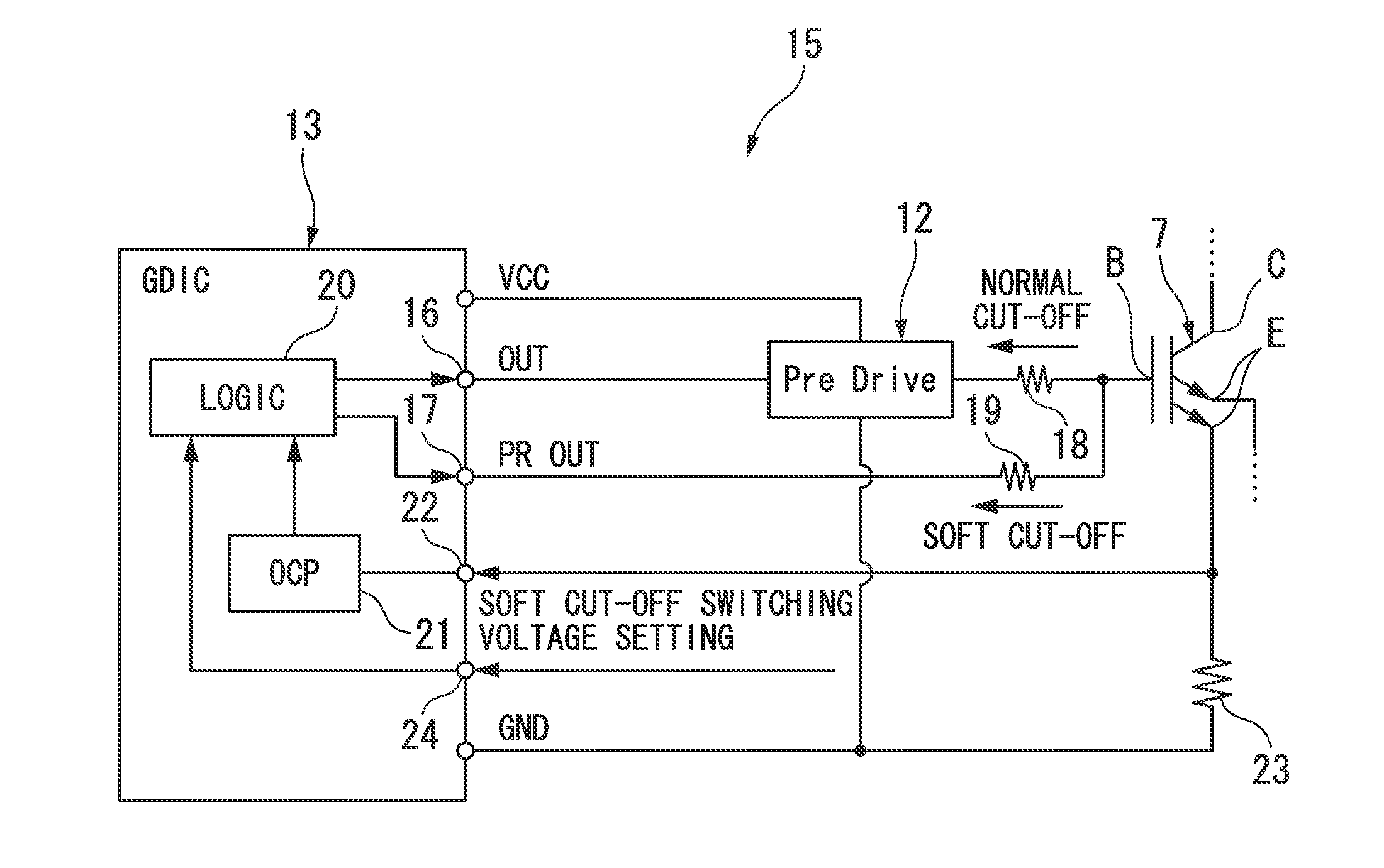
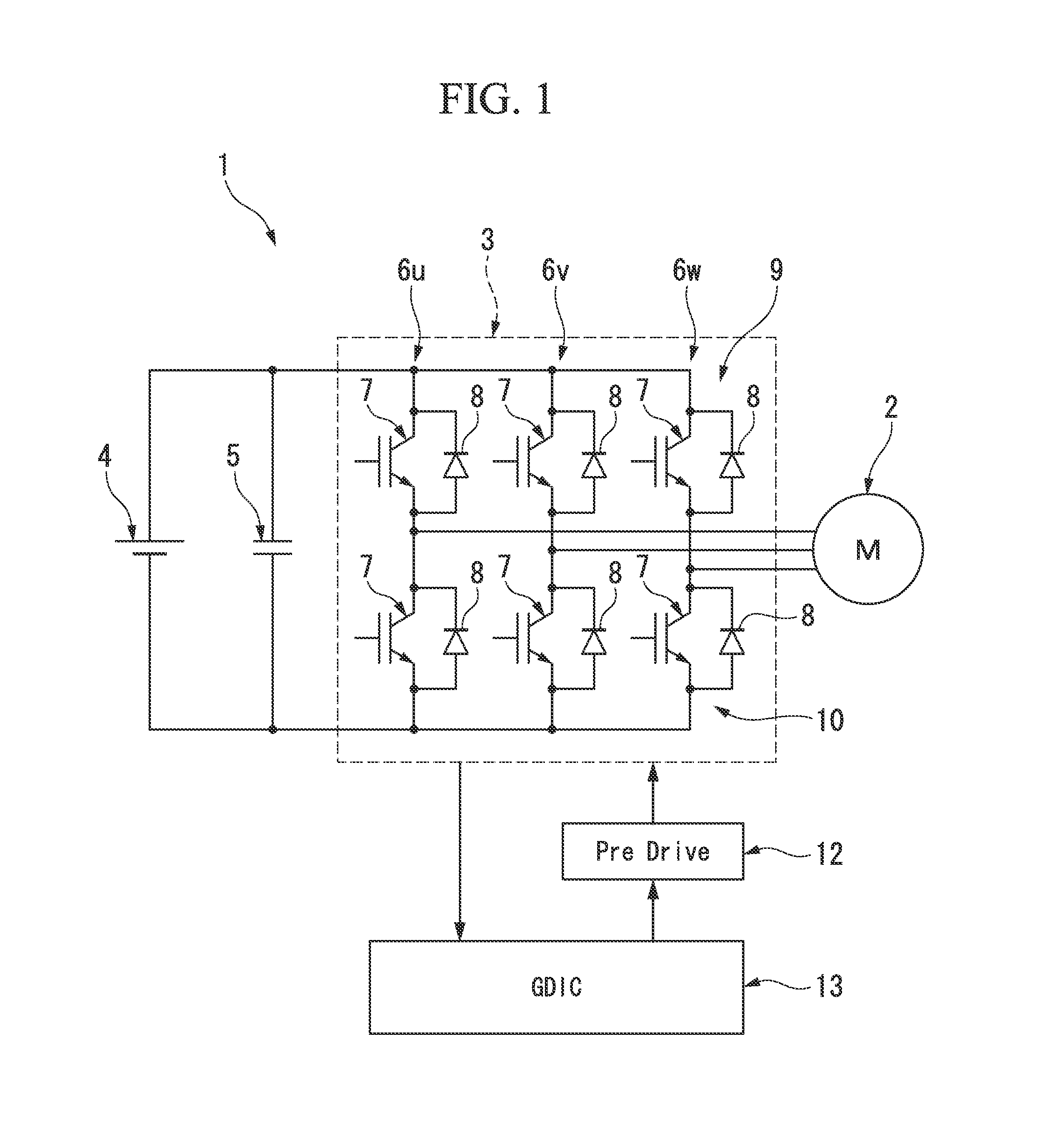
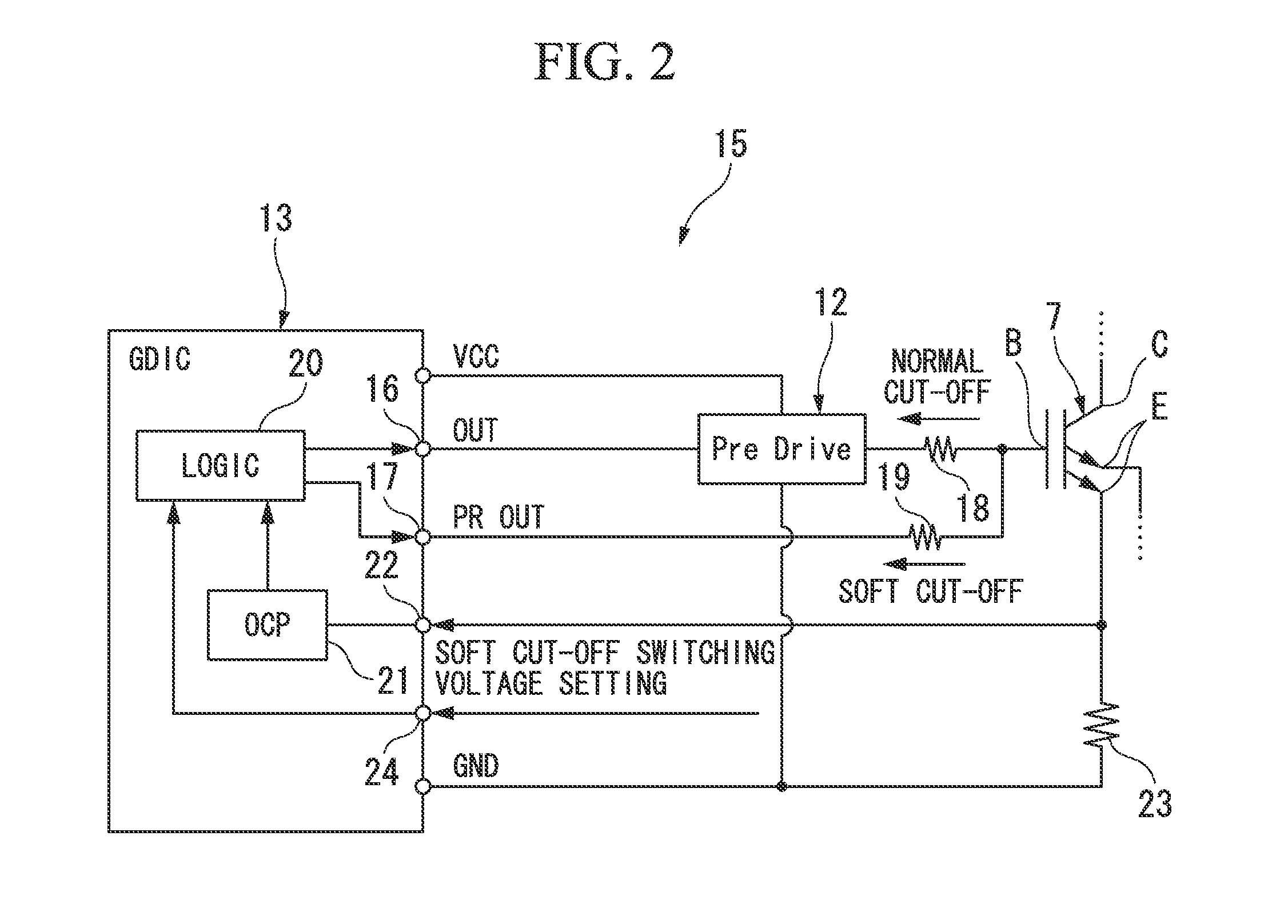
[0040]That is, according to the above-described first embodiment, as shown in FIG. 4, when overcurrent (short-circuit) is detected in one of the power switching elements 7 of the upper arm 9 and the lower arm 10, the logic circuit 20 starts the gate cut-off process (cut-off process) of cutting off the gate of the other power switching element of the upper arm 9 and the lower arm 10, and starts the normal gate cut-off using the first gate resistor 18 and compares the collector voltage and the soft cut-off switching voltage to each other. As a result of the comparison, when the collector voltage does not reach the soft cut-off switching voltage, the normal cut-off using the first gate resistor 18 is continued, and when the collector voltage reaches soft cut-off switching voltage, the cut-off is switched to the soft cut-off using the second gate resistor 19.

[0041]Accordingly, in a case where it is detected that a short-circuit fault occurs in one of the power switching elements 7, the ...

second embodiment

[0046]Therefore, when the temperature of the power switching element 7 is detected and this temperature reaches a predetermined threshold temperature, it is determined that the heating of the power switching element 7 is large and the gate resistor is switched from the second gate resistor 19 having a high resistance value to the first gate resistor 18 having a low resistance value. Accordingly, the collector current can drop rapidly and the heating can be suppressed. As a result, as compared to a case where only a single gate resistor having low resistance value is continuously used from start to finish of the gate cut-off process, a time for which only a low resistance value is used can be reduced and thus surge voltage can be suppressed. As a result, the increase in the size of the power switching element 7 or the like can be prevented and the gate G can be rapidly cut off with a simple circuit configuration.

[0047]In the above-described short-circuit protection methods according...


PUM


Abstract

A short-circuit protection method for a circuit having a plurality of power switching elements, includes, when a short-circuit of a first power switching element is detected by detection device that detects a short-circuit of the plurality of power switching elements, performing a cut-off process of cutting off a gate of a second power switching element through which a short-circuit current caused by the short-circuit of the first power switching element flows, and changing a resistance value of a gate resistor of the second power switching element while the cut-off process is performed.

Description

TECHNICAL FIELD[0001]The present invention relates to a short-circuit protection method using a power switching element or the like.[0002]Priority is claimed on Japanese Patent Application No. 2010-093530, filed Apr. 14, 2010, the content of which is incorporated herein by reference.BACKGROUND ART[0003]In vehicles such as electric vehicles or hybrid vehicles which travel through the driving of a motor, the motor is controlled using an inverter in which power switching elements are bridge-connected to each other. For example, when a short-circuit fault occurs in one of the power switching elements of an upper arm and a lower arm of an inverter, in order to prevent a large short-circuit current from flowing, a short-circuit protection method of cutting off a gate of the other power switching element of the upper arm and the lower arm where a short-circuit fault has not occurred, is known.[0004]In general, the shorter a response time of a power switching element, the greater the rate o...

Claims


Application Information

Patent Timeline
Patent Type & Authority Applications(United States)
IPC IPC(8): H02H3/087
CPCH02M1/08H02M1/32H03K17/168H02H3/087H03K17/163H03K17/0828
Inventor HASHIMOTO, JUNICHISHINOHARA, SADAO
Owner HONDA MOTOR CO LTD
Why Eureka
Try Eureka