Drainage treatment system

Inactive Publication Date: 2018-04-26
ROTHLEITNER CRAIG
View PDF1 Cites 3 Cited by
  • Summary
  • Abstract
  • Description
  • Claims
  • Application Information

AI Technical Summary

Benefits of technology

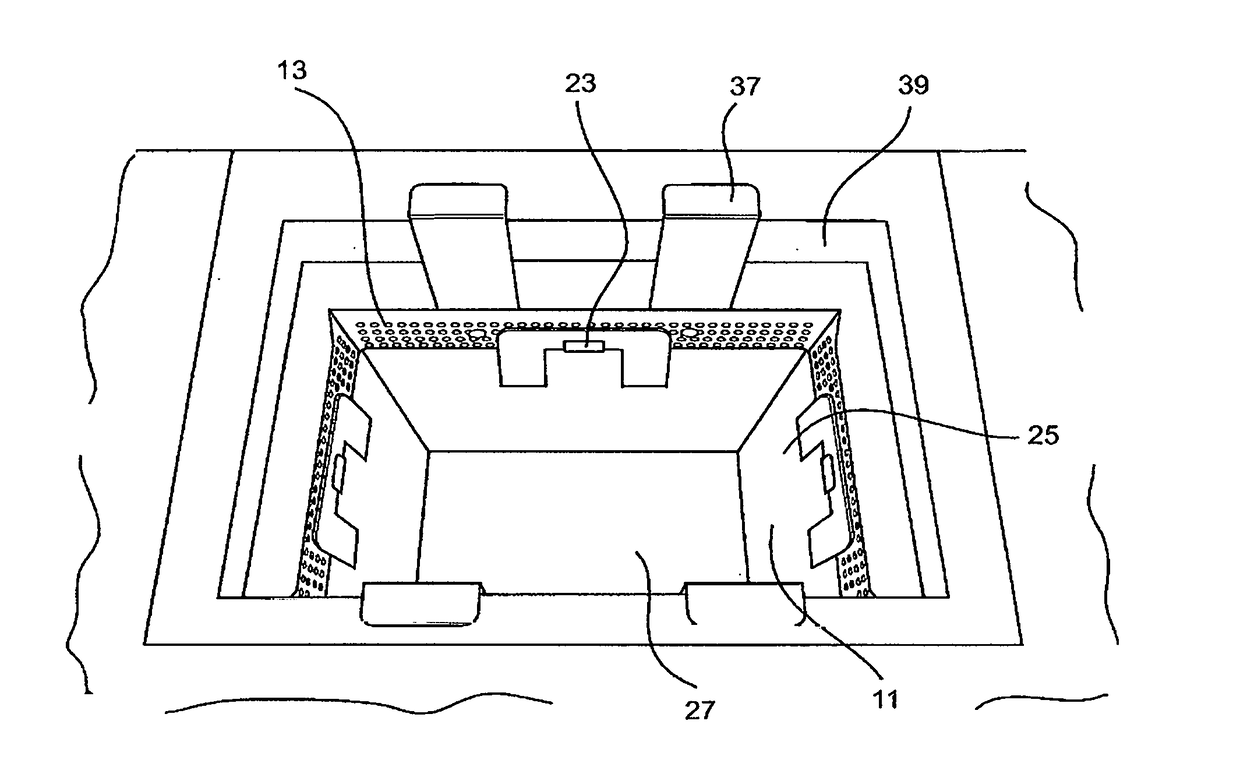
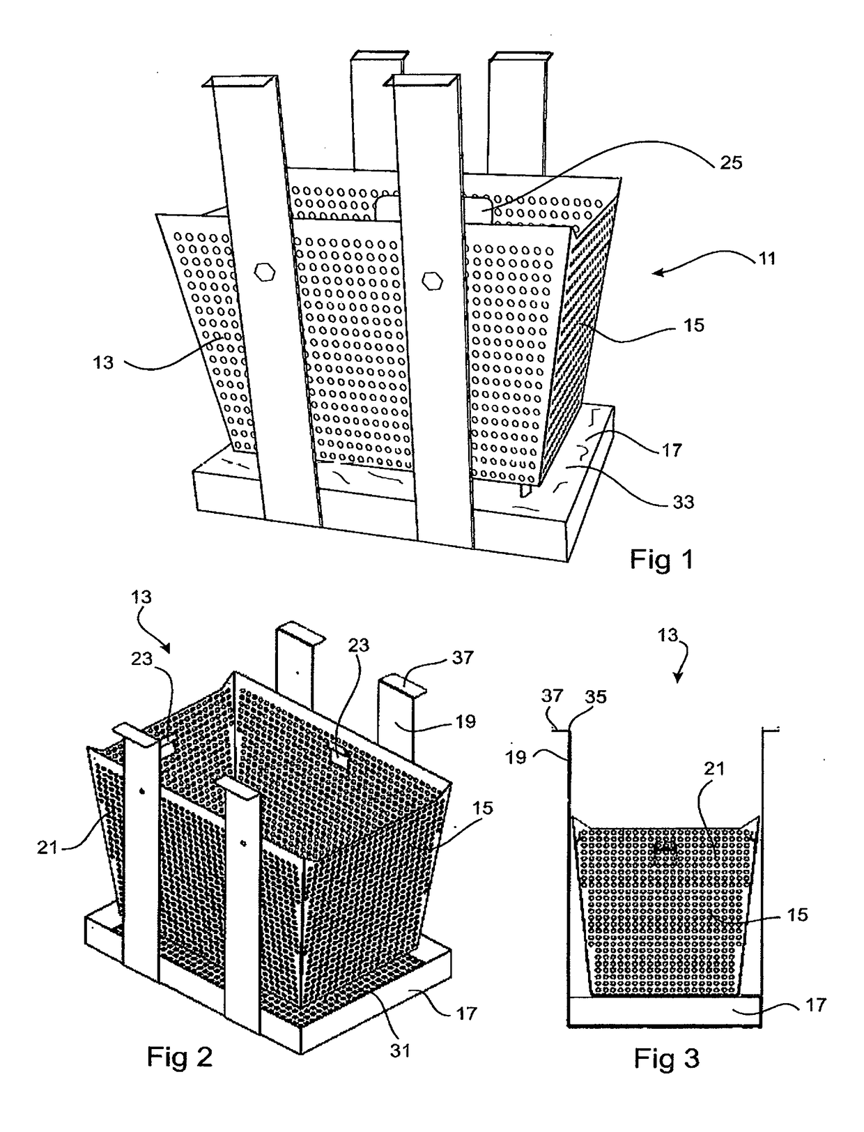
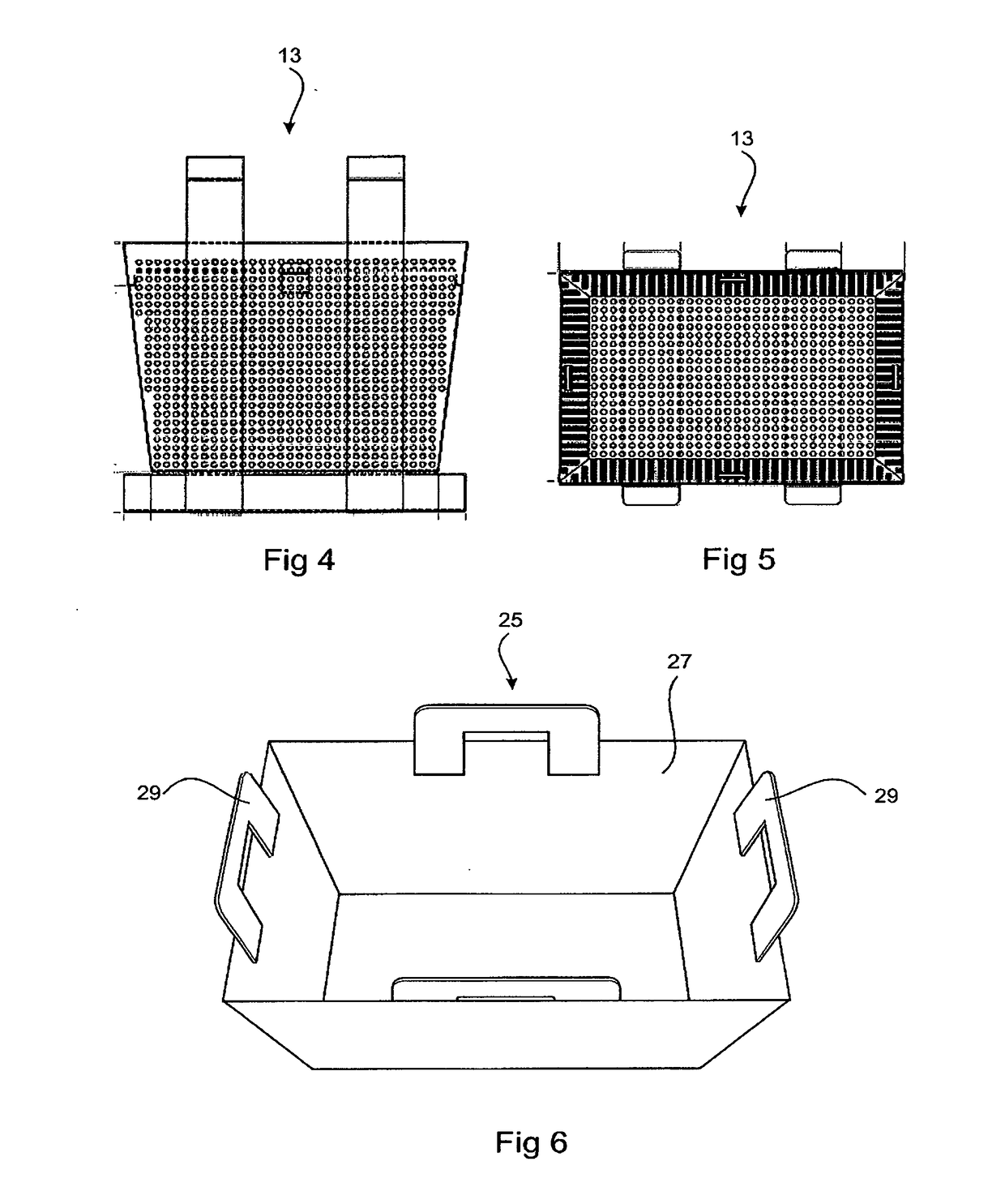
[0008]An example embodiment of the present invention is directed to a drainage treatment system for minimizing debris entering a drainage system. The system includes a support housing adapted to be supportingly received in the drainage system downstream of an opening thereof, the support housing including a first drainage means for allowing liquid to flow therethrough. The system includes a first insert for collecting debris, the first insert including a second drainage means for allowing liquid to flow therethrough while preventing the flow through of debris. The first insert is removably supported within the housing such that when in place, the first and second drainage means allow liquid to pass through the drainage treatment system. The debris collected in the

Problems solved by technology

A common problem associated with drainage systems is the tendency for debris to collect in the drainage system.
Eventually the drainage system becomes blocked due to the debris which has accumulated in the system.
This can be extremely hazardous, particularly where traffic is involved.
Debris passing though drainage systems can also be problematic in water treatment facilities, and may also leak from the drainage system and prove hazardous to the environment.
These systems are complicated in their construction and do not allow for the easy removal of debris collected therein.
Furthermore the plates/screens also restrict the flow of liquid able to pass throug

Method used


Image

  • Drainage treatment system
  • Drainage treatment system
  • Drainage treatment system

Examples


Embodiment Construction

[0031]In the following description, certain specific details are set forth in order to provide a thorough understanding of various example embodiments of the disclosure. However, one skilled in the art will understand that the disclosure may be practiced without these specific details. In other instances, well-known structures associated with manufacturing techniques have not been described in detail to avoid unnecessarily obscuring the descriptions of the example embodiments of the present disclosure.

[0032]Unless the context requires otherwise, throughout the specification and claims that follow, the word “comprise” and variations thereof, such as “comprises” and “comprising,” are to be construed in an open, inclusive sense, that is, as “including, but not limited to.”

[0033]Reference throughout this specification to “one example embodiment” or “an embodiment” means that a particular feature, structure or characteristic described in connection with the embodiment is included in at l...


PUM


Abstract

A drainage treatment system for minimizing debris entering a drainage system is described herein, the system including a support housing supportingly received in the drainage system downstream of an opening thereof. The support housing includes a first drainage means for allowing liquid to flow therethrough. The system also includes a first insert for collecting debris, the first insert having a second drainage means for allowing liquid to flow therethrough while preventing the flow through of debris. The first insert is removably supported within the housing such that when in place, the first and second drainage means align, permitting liquid to pass through the drainage treatment system. In use, debris collects in the system and is removed therefrom by removing the first insert from the support housing.

Description

CROSS-REFERENCE TO RELATED PATENT APPLICATIONS[0001]The present continuation-in-part application claims the benefit under 35 U.S.C. § 120 of co-pending and commonly assigned U.S. patent application Ser. No. 14 / 143,940 to the inventor, filed Dec. 30, 2013, pending, which in turn is a 371 national phase entry of international Appl. Ser. No. PCT / AU2011 / 000788 by the inventor, filed Jun. 28, 2011. The present continuation-in-part application additionally claims priority under 35 U.S.C. § 119(b) to Australian Pat. Appl. Ser. No. 2014200454, filed Jan. 28, 2014, pending. The entire contents of each application noted above are hereby incorporated by reference herein.BACKGROUNDField[0002]Example embodiments of the present invention generally relate to a drainage treatment system for use in drainage systems, more particularly to a system which collects debris entering a drain for easy removal therefrom.Related Art[0003]A common problem associated with drainage systems is the tendency for deb...

Claims


Application Information

Patent Timeline
IPC IPC(8): E03F5/04
CPCE03F5/0404
Inventor ROTHLEITNER, CRAIG
Owner ROTHLEITNER CRAIG
Why Eureka
Try Eureka