
Multi-bit flip-flops and scan chain circuits

a multi-bit flip-flop and chain circuit technology, applied in the field of logic circuits, can solve the problem that the conventional mater-slave flip-flop cannot meet the low power level, and achieve the effect of facilitating scan tests and reducing power consumption

Active Publication Date: 2016-10-18
SAMSUNG ELECTRONICS CO LTD
View PDF26 Cites 7 Cited by
  • Summary
  • Abstract
  • Description
  • Claims
  • Application Information

AI Technical Summary

Benefits of technology

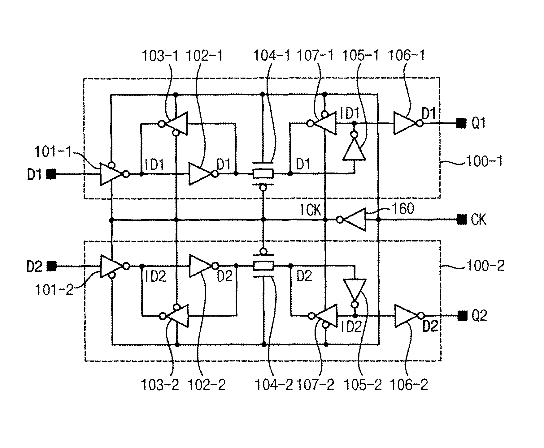
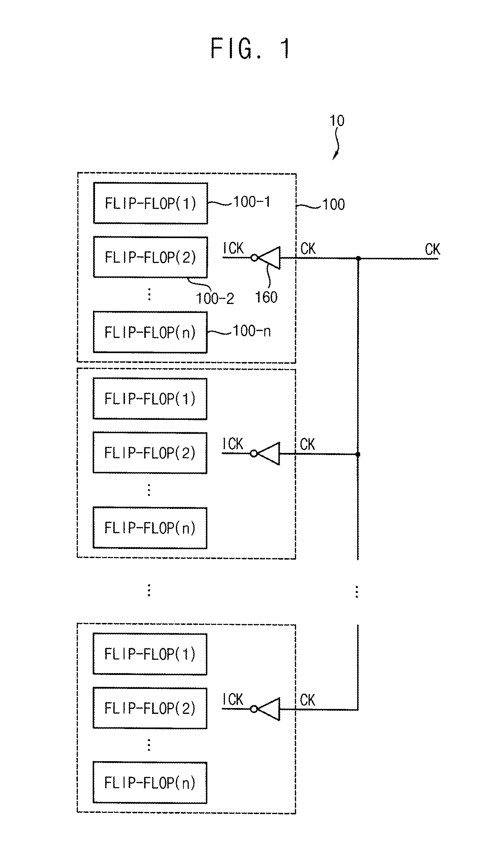
The patent describes a multi-bit flip-flop that can operate at low power by minimizing power consumption in the clock path. This flip-flop includes multi-bit flip-flop blocks that share the clock signal, allowing for efficient operation. Additionally, the patent discusses a scan chain circuit that utilizes this multi-bit flip-flop to facilitate a scan test for the integrated circuit. Overall, the patent provides a way to reduce power consumption and improve the efficiency of flip-flop circuits and scan chain circuits.

Problems solved by technology

However, since a conventional mater-slave flip-flop consumes much power in a clock path whenever a clock signal is toggled, the conventional mater-slave flip-flop cannot satisfy low power level that a recent mobile device of which an operating frequency is relatively high requires.

Method used


Image

  • Multi-bit flip-flops and scan chain circuits
  • Multi-bit flip-flops and scan chain circuits
  • Multi-bit flip-flops and scan chain circuits

Examples


Embodiment Construction

[0054]Various example embodiments will be described more fully with reference to the accompanying drawings, in which some example embodiments are shown. The present inventive concepts may, however, be embodied in many different forms and should not be construed as limited to the example embodiments set forth herein. Rather, these example embodiments are provided so that this disclosure will be thorough and complete, and will fully convey the scope of the present inventive concepts to those skilled in the art. Like reference numerals refer to like elements throughout this application.

[0055]It will be understood that, although the terms first, second, etc. may be used herein to describe various elements, these elements should not be limited by these terms. These terms are used to distinguish one element from another. For example, a first element could be termed a second element, and, similarly, a second element could be termed a first element, without departing from the scope of the p...


PUM


Abstract

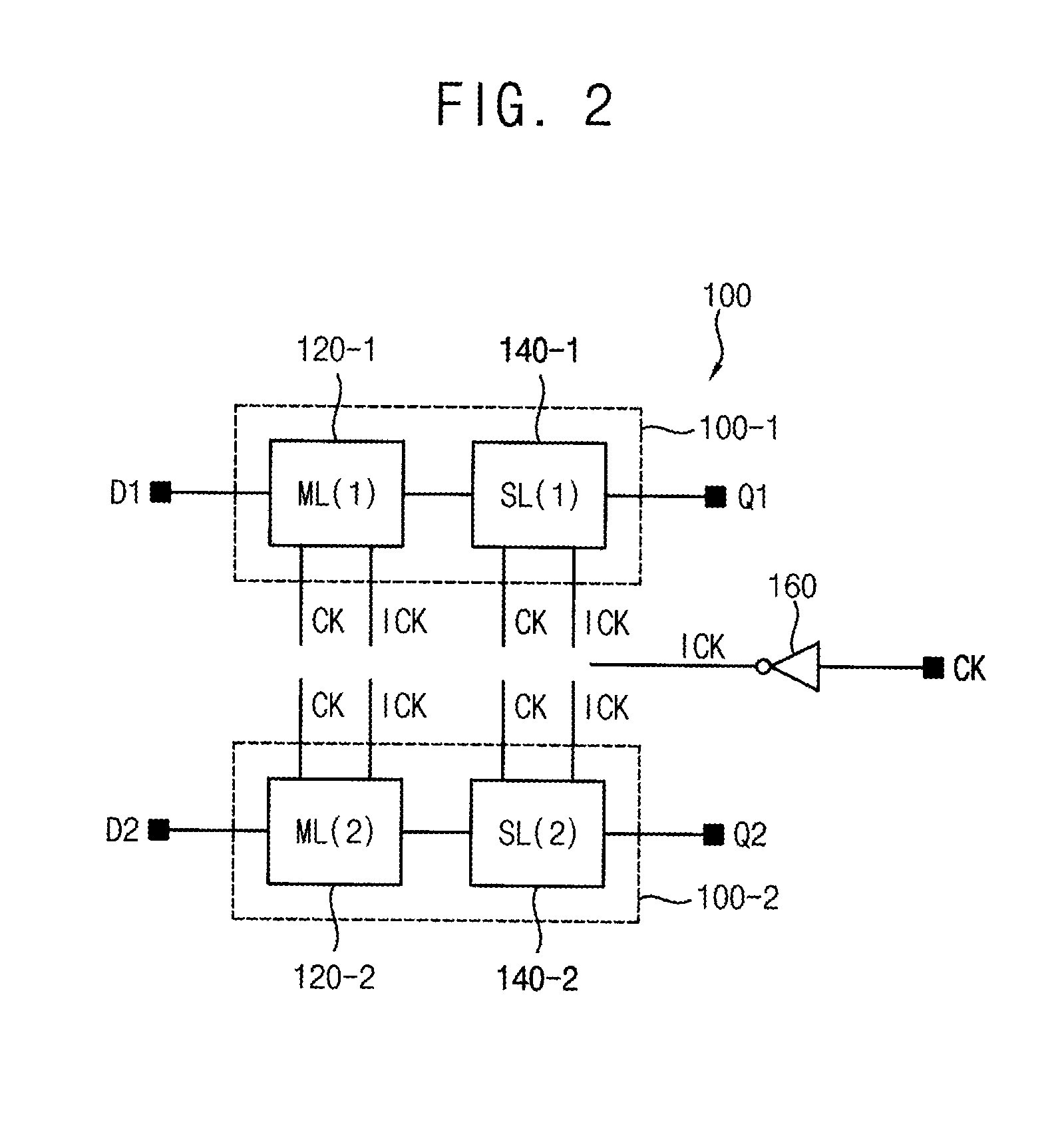
A multi-bit flip-flop includes a plurality of multi-bit flip-flop blocks that share a clock signal. Each of the multi-bit flip-flop blocks includes a single inverter and a plurality of flip-flops. The single inverter generates an inverted clock signal by inverting the clock signal. Each of the flip-flops includes a master latch part and a slave latch part and operates the master latch part and the slave latch part based on the clock signal and the inverted clock signal. Here, the flip-flops are triggered at rising edges of the clock signal. Thus, the multi-bit flip-flop operating as a master-slave flip-flop may minimize (or, reduce) power consumption occurring in a clock path through which the clock signal is transmitted.

Description

BACKGROUND[0001]1. Technical Field[0002]Example embodiments relate generally to a logic circuit. More particularly, embodiments of the present inventive concepts relate to a multi-bit flip-flop that operates as a master-slave flip-flop and a scan chain circuit having a structure based on the multi-bit flip-flop.[0003]2. Description of the Related Art[0004]Recently, according to a mobile convergence trend, there is a rising interest on a low power technology for a mobile device (e.g., a smart phone, a smart pad, etc.). Generally, since the mobile device uses a limited power such as a battery, manufacturing (or, designing) the mobile device with low power chips including low power flip-flops is necessary as well as efficient power management for the mobile device to consume low power. A master-slave flip-flop has been used for a long time because a size of the master-slave flip-flop is relatively small and the mater-slave flip-flop has high reliability. However, since a conventional m...

Claims


Application Information

Patent Timeline
Patent Type & Authority Patents(United States)
IPC IPC(8): H03K3/00H03K3/037H03K19/21G01R31/3177
CPCH03K3/0372G01R31/3177H03K19/21G01R31/318541H03K3/35625Y02D30/70G01R31/318536H03K3/3562H03K3/356G01R31/31723G01R31/31727
Inventor KIM, MIN-SUBERZINS, MATTHEWKIM, JONG-WOO
Owner SAMSUNG ELECTRONICS CO LTD
Learn More