
Vented stop bead apparatus, vented weep screed apparatus, and related systems and methods thereof

a technology of weep screed and stop bead, which is applied in the field of casing beads and weep screeds, can solve the problems of significant additional repair costs and frustration for home owners and construction companies, adds considerably to the cost and duration of construction, and is very time-consuming

Active Publication Date: 2018-04-26
E Z BEAD
View PDF19 Cites 13 Cited by
  • Summary
  • Abstract
  • Description
  • Claims
  • Application Information

AI Technical Summary

Benefits of technology

The present invention provides a system and method for a vented stop bead apparatus, which helps to prevent water damage to building materials, such as stuccos and plaster walls. The apparatus includes a base panel and two walls that form a cavity where water can accumulate. A vented portion is positioned between the two walls and has a venting structure that allows air to escape while preventing water from entering. A rain screen is also included to help direct the venting path and prevent water from entering the cavity. This system helps to prevent water damage and improve the durability of building materials.

Problems solved by technology

This process that is used by some builders to prevent leaks is very time consuming.
This method of stucco installation has often resulted in leaking problems between the stucco or plaster surface and the adjacent jamb, thereby causing significant additional repair costs and frustration to both home owners and construction companies.
In addition, the extra time and materials necessary for installation of the backer rod and finishing caulk layer can add considerably to the costs and duration of the construction.
However, even with products designed to allow venting of moisture from stucco or plaster walls, these walls still have moisture and venting problems.
Thus, a heretofore unaddressed need exists in the industry to address the aforementioned deficiencies and inadequacies.

Method used


Image

  • Vented stop bead apparatus, vented weep screed apparatus, and related systems and methods thereof
  • Vented stop bead apparatus, vented weep screed apparatus, and related systems and methods thereof
  • Vented stop bead apparatus, vented weep screed apparatus, and related systems and methods thereof

Examples


Embodiment Construction

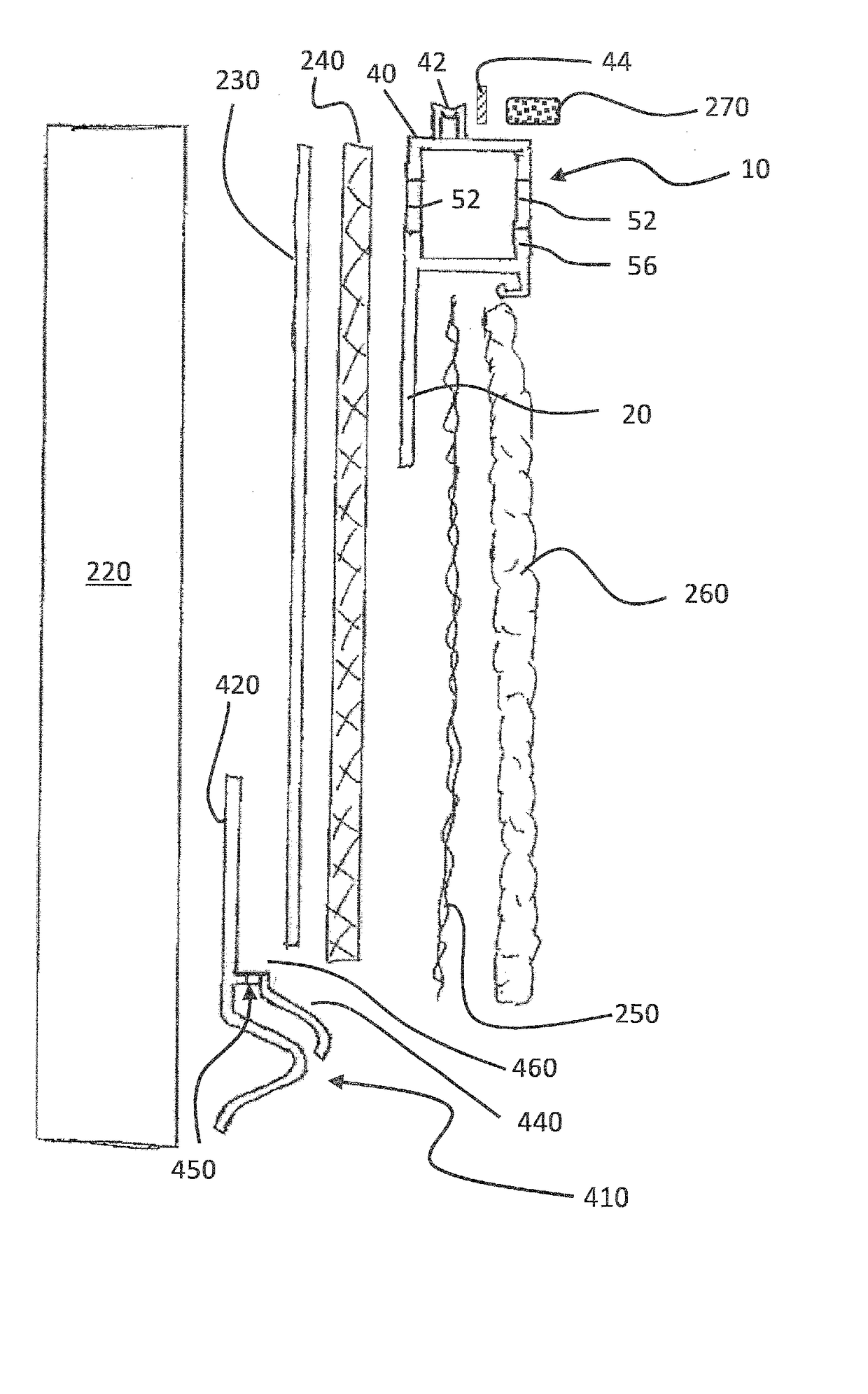
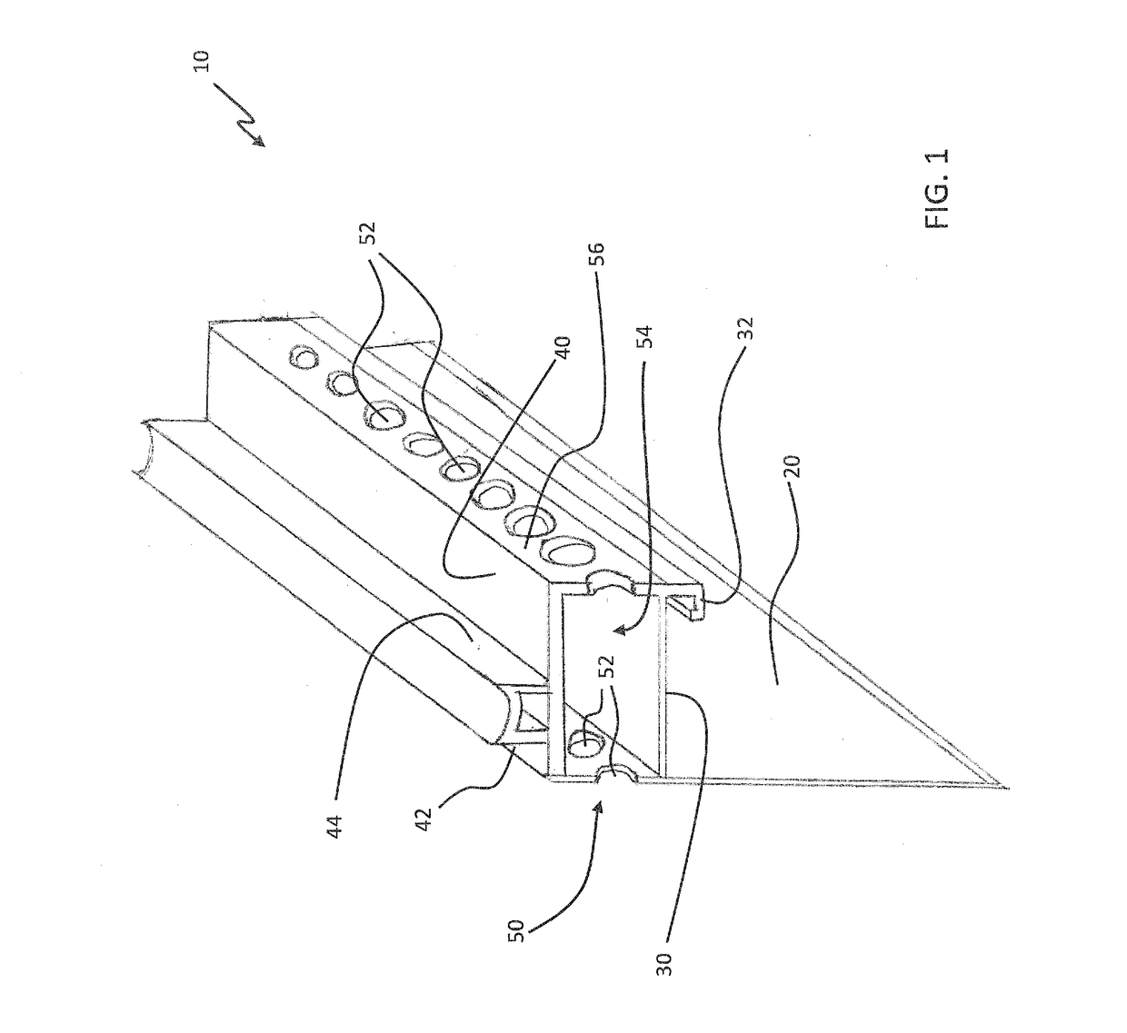
[0025]FIG. 1 is an elevated, side-view, cross-sectional illustration of a vented stop bead apparatus 10, in accordance with a first exemplary embodiment of the present disclosure. The vented stop bead apparatus 10, which may be referred to herein simply as ‘apparatus 10’ or as ‘casing bead apparatus’, has a base panel 20. A stop bead wall 30 extends from the base panel 20 at a first location. A spacing member wall 40 extends from the base panel 20 at a second location. A spacing member 42 is connected to the spacing member wall 40. A vented portion 50 is positioned between the stop bead wall 30 and the spacing member wall 40, wherein the vented portion 50 has at least one venting structure 52 positioned through the base panel 20 in a position between the first and second locations.

[0026]Conventionally, leaking and other problems often occur where the stucco or plaster finish aligns with other design constructs of the home or building, such as windows or doors. Stop strips which cont...


PUM

PropertyMeasurementUnit
structureaaaaaaaaaa
angleaaaaaaaaaa
timeaaaaaaaaaa

Abstract

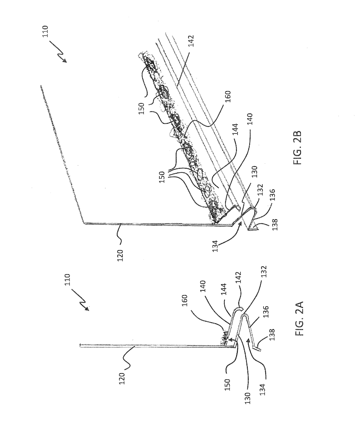
A vented stop bead and a vented weep screed are used to vent a stucco or plaster wall. The vented stop bead has a base panel with a stop bead wall extending from the base panel at a first location and a spacing member wall extending from the base panel at a second location, wherein a spacing member is connected to the spacing member wall. A vented portion is positioned between the stop bead wall and the spacing member wall, wherein the vented portion has a venting structure positioned through the base panel between the first and second locations. The vented weep screed has a nailing fin with a first leg extending therefrom at a first location. A second leg extends from the nailing fin at a second location, the second leg having at least one venting structure positioned through the second leg.

Description

CROSS REFERENCE TO RELATED APPLICATION[0001]This application claims benefit of U.S. Provisional Application Ser. No. 62 / 412,710 entitled, “Vented stop bead apparatus, vented weep screed apparatus, and related systems and methods thereof” filed Oct. 25, 2016, U.S. Provisional Application Ser. No. 62 / 443,405 entitled, “Vented stop bead apparatus, vented weep screed apparatus, and related systems and methods thereof” filed Jan. 6, 2017, and U.S. Provisional Application Ser. No. 62 / 472,297 entitled, “Vented stop bead apparatus, vented weep screed apparatus, and related systems and methods thereof” filed Mar. 16, 2017, the entire disclosures of which are incorporated herein by reference.FIELD OF THE DISCLOSURE[0002]The present disclosure is generally related to casing beads and weep screeds, and more particularly is related to vented stop bead apparatuses, vented weep screed apparatuses, and related systems and methods thereof.BACKGROUND OF THE DISCLOSURE[0003]Stucco and / or plaster are t...

Claims


Application Information

Patent Timeline
Patent Type & Authority Applications(United States)
IPC IPC(8): E04F13/04E04F13/06E06B7/23E06B1/62
CPCE04F13/045E04F13/06E06B7/2303E04F13/068E06B1/62E06B1/02E06B2001/624E04F19/061
Inventor MAZIARZ, JEFFREY
Owner E Z BEAD
Learn More