Blind rivet nut
- Summary
- Abstract
- Description
- Claims
- Application Information
AI Technical Summary
Benefits of technology
Problems solved by technology
Method used
Image

Examples
second embodiment
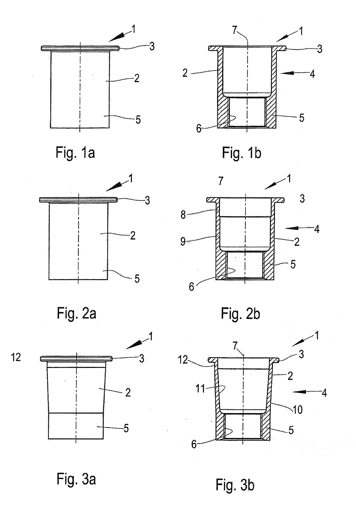
[0048]FIGS. 2a and 2b show a modified, second embodiment of a blind rivet nut 1 (FIG. 2a in a side view, FIG. 2b in a sectional view) which differs from the embodiment according to FIGS. 1a and 1b in that the rivet sleeve 2 has at least two different wall thicknesses between the set head 3 and the threaded section 5. In this exemplary embodiment, the deformation section 4 has a smaller wall thickness in a section 8 adjacent to the set head 3 than in a section 9 adjacent to the threaded section 5. When the blind rivet nut 1 is set, the section 8 adjacent to the set head 3 is at least partially surrounded by the item that is to be joined, so that this section 8 is stabilized by the item that is to be joined. The section 9 adjacent to the threaded section 5 forms the closing head. Apart from that, this blind rivet nut 1 has the same properties and features as the blind rivet nut 1 described in connection with FIGS. 1a and 1b.
third embodiment
[0049]FIGS. 3a and 3b show a blind rivet nut 1 (FIG. 3a in a side view, FIG. 3b in a sectional view) in which in a section between the set head 3 and the threaded section 5, the rivet sleeve 2 comprises an outer circumferential wall 10 that tapers towards the threaded section 5. In the embodiment according to FIGS. 3a and 3b, the outer circumferential wall is embodied to be conical.
[0050]The female thread 6 of the threaded section 5 has the same diameter as in the embodiments according to FIGS. 1a, 1b, 2a and 2b. However, it can be seen that the wall of the threaded section 5, which bears the female thread 6, has a smaller thickness than the wall in the embodiment according to FIGS. 1a, 1b, 2a and 2b as a result of the tapering shape of the rivet sleeve 2.
[0051]In this embodiment according to FIGS. 3a and 3b, the rivet sleeve 2 also has a smaller wall thickness adjacent to the set head 3 than adjacent to the threaded section 5.
[0052]In the following exemplary embodiment, between the...
fourth embodiment
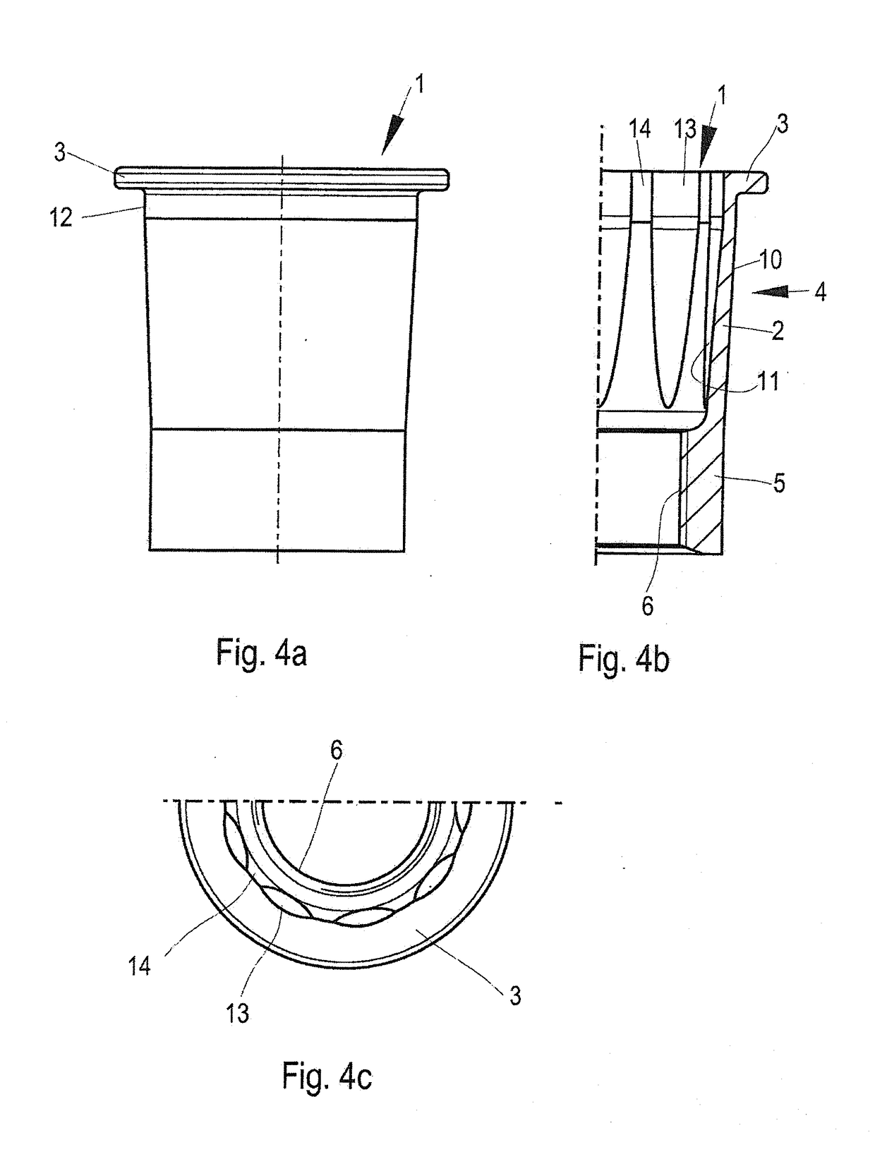
[0054]FIGS. 4a, 4b and 4c show a blind rivet nut 1. From the outside, this blind rivet nut 1 corresponds to the blind rivet nut illustrated in FIG. 3a. FIG. 4a shows a side view, FIG. 4b shows a sectional view of a half, and FIG. 4c shows a top view. The embodiment according to FIGS. 4a, 4b and 4c differs from the embodiment according to FIGS. 3a and 3b in that the rivet sleeve 2 comprises protrusions and troughs 14 (or depressions) on the inner circumferential wall thereof. The protrusions and troughs 14 alternate in a circumferential direction. The protrusions and troughs 14 are located roughly on a circular line. The main direction of the protrusions and the troughs 14 runs parallel to the thread axis 7.
PUM
 Abstract
Description
Claims
Application Information
 - Generate Ideas
- Intellectual Property
- Life Sciences
- Materials
- Tech Scout
- Unparalleled Data Quality
- Higher Quality Content
- 60% Fewer Hallucinations
Browse by: Latest US Patents, China's latest patents, Technical Efficacy Thesaurus, Application Domain, Technology Topic, Popular Technical Reports.
© 2025 PatSnap. All rights reserved.Legal|Privacy policy|Modern Slavery Act Transparency Statement|Sitemap|About US| Contact US: help@patsnap.com