Trackball for touch sensor

Active Publication Date: 2018-05-03
ADVANCED SILICON
View PDF2 Cites 2 Cited by
  • Summary
  • Abstract
  • Description
  • Claims
  • Application Information

AI Technical Summary

Benefits of technology

[0013]Therefore, it is an object to simplify the detecti

Problems solved by technology

The problem of trackballs in the state of the art is their complexity due

Method used


Image

  • Trackball for touch sensor
  • Trackball for touch sensor
  • Trackball for touch sensor

Examples


Example

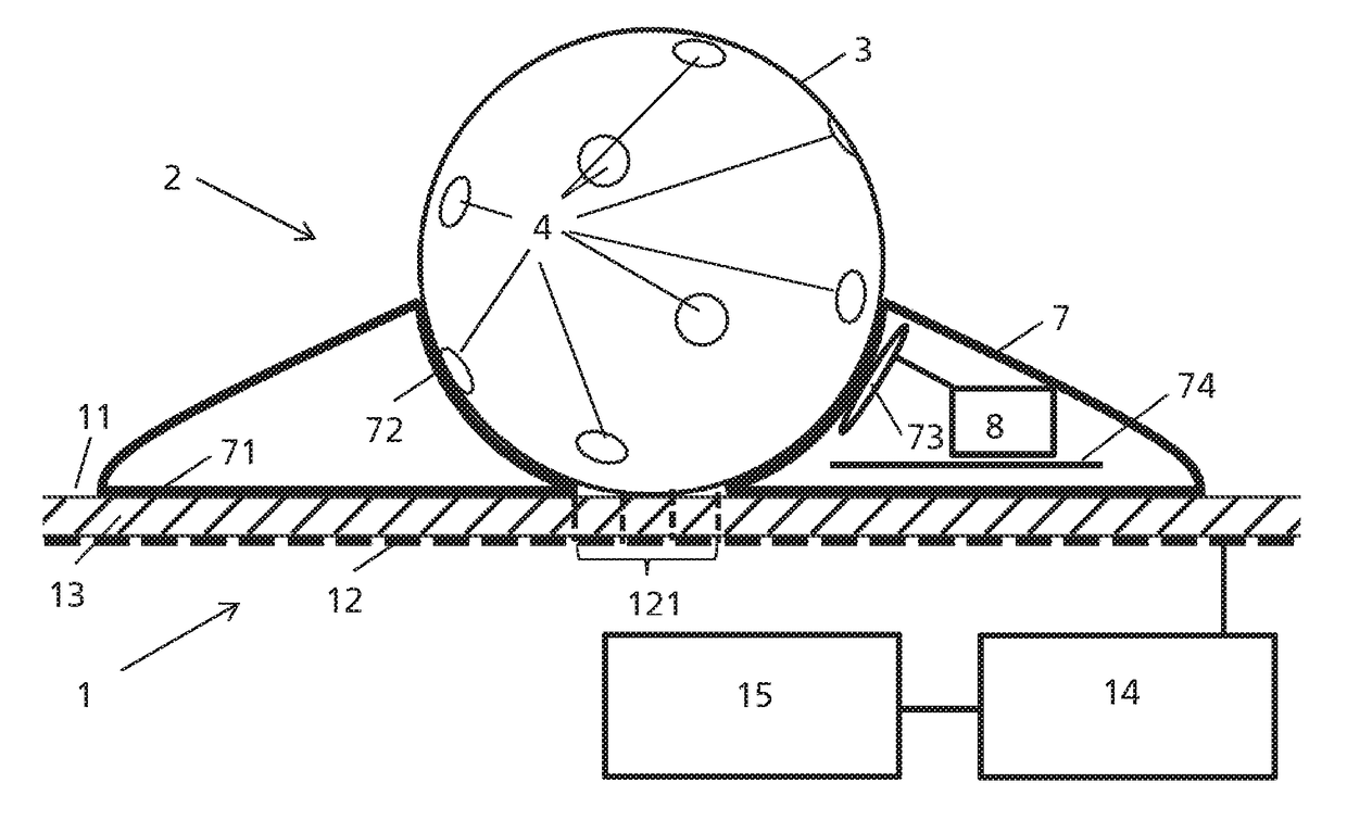
[0033]FIG. 1 shows an embodiment of a system comprising a touch sensor 1, a trackball 2 and a trackball detector 15.

[0034]The touch sensor 1 is configured to detect the position of a touch of an object, e.g. a finger or a pen, on a touch sensor surface 11. Such a touch on the touch sensor surface 11 could be detected, when the object directly contacts the touch sensor surface 11 or also when the object comes only into close vicinity to the touch sensor surface 11. The touch sensor surface 11 is preferably flat. The touch sensor surface 11 comprises a field of touch pixels 12 distributed over the touch sensor surface 11. Each touch pixel 12 can detect a physical value indicating the presence of a touch. The physical value is preferably a capacitance value, but could also be an electrical resistance, a pressure, etc. The field of touch pixels 12 is normally two-dimensional, i.e. comprises rows and columns of touch pixels 12. The touch sensor 1 comprises preferably a touch pixel detect...


PUM


Abstract

System comprising a touch sensor, a trackball and a trackball detector, wherein the trackball comprises a support structure and a ball and is arranged on the touch sensor such that the ball is rotatably supported over the touch sensor surface, wherein a surface of the ball comprises a pattern of detection portions, wherein the touch sensor is configured to detect a position of a touch of an object on a touch sensor surface of the touch sensor, wherein the trackball detector is configured to detect the rotational movement and/or the rotational orientation of the ball on the basis of a movement and/or a position of at least one of the detection portions detected on the touch sensor surface.

Description

RELATED APPLICATIONS[0001]This application claims the benefit of Swiss Application No. 01448 / 16, filed on Oct. 28, 2016, and European Application No. 17159703, filed on Mar. 7, 2017. The entire contents of those applications are incorporated herein by reference.FIELD OF THE INVENTION[0002]The present invention concerns trackballs for touch sensors.DESCRIPTION OF RELATED ART[0003]Trackballs as user input are well known. The trackball comprises normally a support structure and a ball rotatably supported in the support structure. The trackball comprises further movement sensors for detecting the change of the rotational position of the ball, e.g. two rollers detecting the polar and azimuth angle. The trackball is connected electrically to an electronic device which receives the detected change of the rotational position of the ball to control the electronic device.[0004]US2014 / 002362 discloses such a trackball which in addition has a capacitive touch detector for detecting the number a...

Claims


Application Information

Patent Timeline
IPC IPC(8): G06F3/0354G06F3/044
CPCG06F3/03549G06F3/044G06F3/03547G06F3/0393
Inventor BALLAN, HUSSEINFINE, KEVINPASTRE, MARC
Owner ADVANCED SILICON
Why Eureka
Try Eureka