
Stator having adapted tooth geometry

Active Publication Date: 2018-05-03
EBM PAPST MULFINGEN GMBH & CO KG
View PDF2 Cites 1 Cited by
  • Summary
  • Abstract
  • Description
  • Claims
  • Application Information

AI Technical Summary

Benefits of technology

The patent aims to increase the distance between the stator's coils to reduce the likelihood of arcing and improve safety without negatively affecting performance or increasing noise. It also makes it easier to insulate the stator with insulation material.

Problems solved by technology

This increase in the creepage and clearance distance raises the pollution degree with which the stator and therefore the electric motor can be used.

Method used


Image

  • Stator having adapted tooth geometry
  • Stator having adapted tooth geometry
  • Stator having adapted tooth geometry

Examples


Embodiment Construction

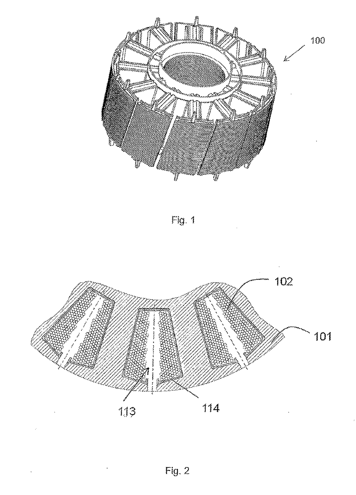
[0033]FIGS. 1 and 2 represent a stator 100 according to the prior art having teeth 101 arranged distributed in the circumferential direction, wherein, between the teeth 101, respective grooves 113 for the accommodation of winding wire 102 are provided. The winding wires 102 are insulated with respect to the stator sheet by an overmolding 114 in the grooves 113. The design represented has a relatively short creepage and clearance distance between the winding wire 102 and the stator sheet of the teeth 101, so that the stator is designed for use with a pollution degree 2. Pollution degree 2 is defined such that only nonconductive pollution occurs, but occasionally temporary conductivity due to condensation is to be expected.

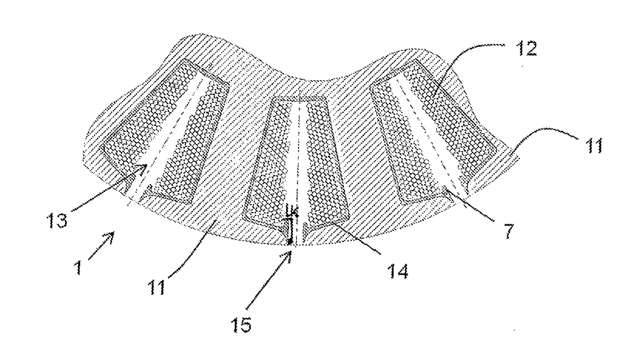
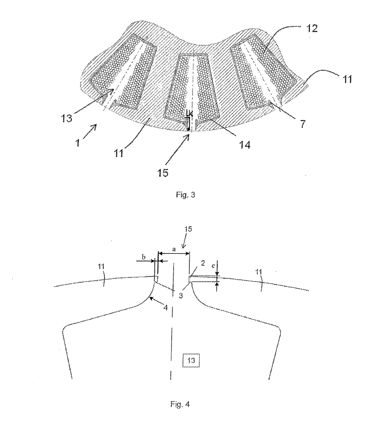
[0034]FIGS. 3 and 4 show an embodiment example of the stator 1 according to the invention as external rotor stator for use with pollution degree 3, which is defined such that conductive pollution or dry non-conductive pollution occurs, which thus also will become co...


PUM


Abstract

The invention relates to a stator of an electric motor, having teeth distributed in the circumferential direction and extending in the radial direction and grooves respectively provided between the teeth, wherein respectively adjacent teeth each form a groove opening at the radial outer edge sections of said teeth, and the radial outer edge sections of the teeth each have a projection extending into the groove opening in the circumferential direction and each forming a free contact surface directed radially inward.

Description

RELATED APPLICATIONS[0001]This application claims priority to German Patent Application No. 10 2015 106 523.1, filed on Apr. 28, 2015; and PCT / EP2016 / 058551 A1, filed Apr. 18, 2016.FIELD[0002]The invention relates to a stator of an electric motor, having teeth distributed in the circumferential direction and extending in the radial direction and grooves respectively provided between the teeth, in which grooves copper wire windings are accommodated.BACKGROUND[0003]Electric motors are used with stators in environments with different pollution degrees. The higher the pollution degree is, the farther the current carrying components have to be removed from conductive components, so that no undesired discharge, i.e., short circuit, occurs. The spacing be maintained is determined here by the creepage and clearance distance, wherein, according to DIN VDE 0110-04.97, the clearance distance is defined as the shortest distance in air between two conductive parts, and the creepage distance is d...

Claims


Application Information

Patent Timeline
IPC IPC(8): H02K1/14
CPCH02K1/146H02K1/165H02K3/325H02K3/345H02K2213/03
Inventor STURM, MICHAEL
Owner EBM PAPST MULFINGEN GMBH & CO KG
Learn More