Envelope tracking current bias circuit and power amplifier apparatus

a current bias circuit and power amplifier technology, applied in the direction of rf amplifiers, amplifier modifications to reduce non-linear distortion, high frequency amplifiers, etc., can solve the problems of low efficiency, low efficiency, and low level of current consumption, so as to reduce the am-pm reduce the amplitude modulation-phase modulation (am-pm) distortion of the power amplifier circui

Active Publication Date: 2018-05-03
SAMSUNG ELECTRO MECHANICS CO LTD
View PDF2 Cites 11 Cited by
  • Summary
  • Abstract
  • Description
  • Claims
  • Application Information

AI Technical Summary

Benefits of technology

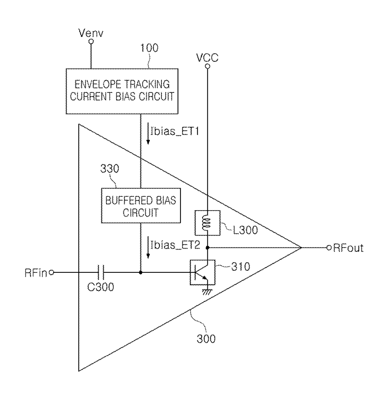
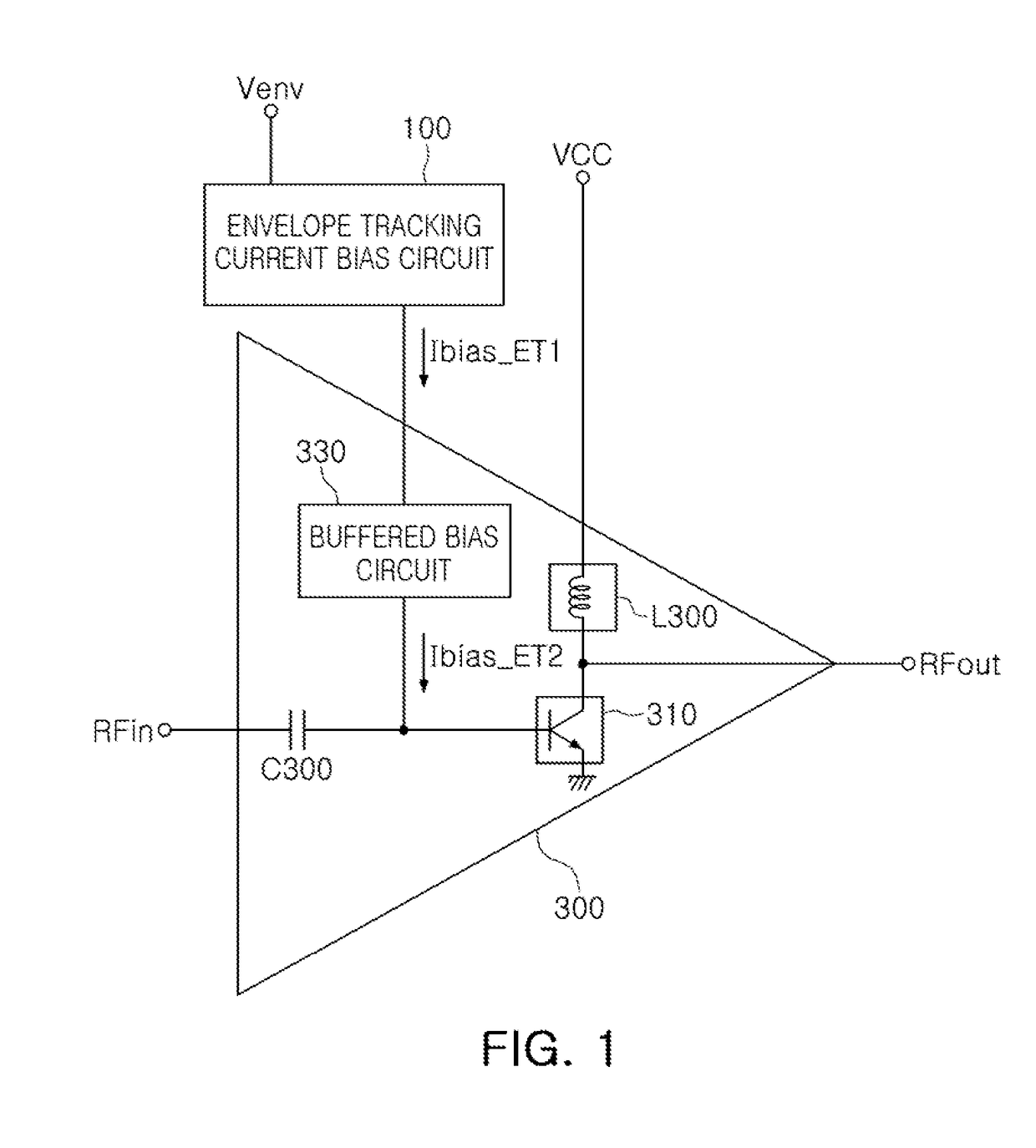
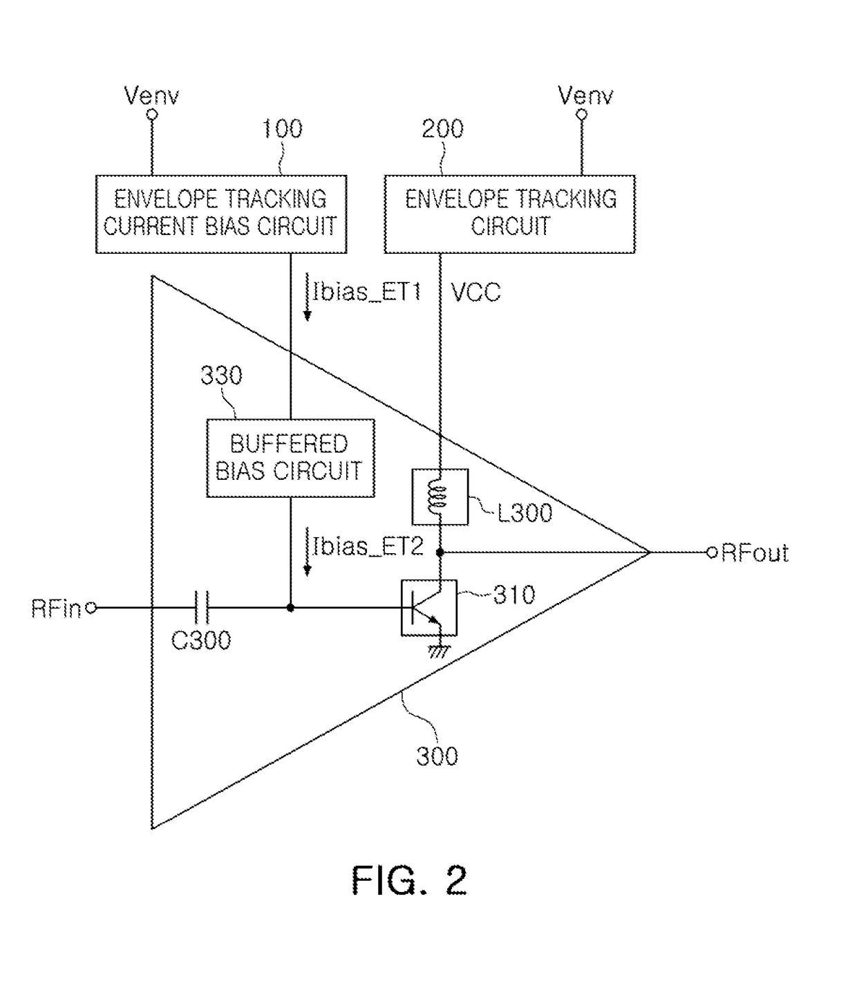
[0032]In another general aspect, a power amplifier apparatus includes a power amplifier circuit configured to amplify an input signal and having a characteristic that produces amplitude modulation-phase modulation (AM-PM) distortion that varies in response to a voltage level of the input signal; and an envelope tracking current bias circuit configured to generate a first tracking bias current based on a fixed reference voltage and an envelope voltage of the input signal, and apply the first tracking bias current to the power amplifier circuit to reduce the AM-PM distortion of the power amplifier circuit.
[0033]The power amplifier circuit may include a power amplifier having a base to which the input signal is applied, and configured to amplify the input signal applied to the base; and a buffered bias circuit configured to amplify the first tracking bias current to generate a second tracking bias current, and apply the second tracking bias current to the base of the power amplifier to reduce the amplitude modulation-phase modulation (AM-PM) distortion of the power amplifier circuit.

Problems solved by technology

However, such PAMs in the related art have not provided a scheme for efficiently supplying a bias current to further reduce current consumption.
However, since such PAMs set a bias current as a fixed value and provide a relatively high level of bias current to provide biasing without deterioration, even in a case in which the power of RF signals is high, the PAMs provide a higher level of bias current than necessary in a case in which the power of RF signals is low, causing a relatively high level of current consumption.
In this case, degradation of amplitude modulation-phase modulation (AM-PM) distortion characteristics of the PAMs may cause deterioration of adjacent channel power ratio (ACPR) performance of the PAMs.

Method used


Image

  • Envelope tracking current bias circuit and power amplifier apparatus
  • Envelope tracking current bias circuit and power amplifier apparatus
  • Envelope tracking current bias circuit and power amplifier apparatus

Examples


Embodiment Construction

[0059]The following detailed description is provided to assist the reader in gaining a comprehensive understanding of the methods, apparatuses, and / or systems described herein. However, various changes, modifications, and equivalents of the methods, apparatuses, and / or systems described herein will be apparent after an understanding of the disclosure of this application. For example, the sequences of operations described herein are merely examples, and are not limited to those set forth herein, but may be changed as will be apparent after an understanding of the disclosure of this application, with the exception of operations necessarily occurring in a certain order. Also, descriptions of functions and constructions that are known in the art may be omitted for increased clarity and conciseness.

[0060]The features described herein may be embodied in different forms, and are not to be construed as being limited to the examples described herein. Rather, the examples described herein hav...


PUM


Abstract

An envelope tracking current bias circuit of a power amplifier circuit including a power amplifier includes a first current source circuit configured to generate a first bias current based on a reference voltage, a second current source circuit configured to generate a second bias current based on an envelope voltage of an input signal, and a bias current generator configured to generate a first envelope tracking bias current based on the first bias current and the second bias current, and supply the first envelope tracking bias current to the power amplifier circuit to reduce amplitude modulation-phase modulation (AM-PM) distortion of the power amplifier circuit.

Description

CROSS-REFERENCE TO RELATED APPLICATIONS[0001]This application claims the benefit under 35 USC 119(a) of Korean Patent Application Nos. 10-2016-0141913 filed on Oct. 28, 2016, and 10-2016-0156628 filed on Nov. 23, 2016, in the Korean Intellectual Property Office, the entire disclosures of which are incorporated herein by reference for all purposes.BACKGROUND1. Field[0002]This application relates to an envelope tracking current bias circuit and a power amplifier apparatus that may be applied to a communications system.2. Description of Related Art[0003]In general, power amplifier modules (PAMs) amplify radio frequency (RF) signals in transmitters and transmit the amplified RF signals to antennas. Because such PAMs support a wide range of frequency bands, the PAMs may include a plurality of switches, a plurality of filters, and a plurality of power amplifiers (PAs) amplifying RF signals.[0004]The performance of PAMs may be evaluated by maximum output, efficiency, linearity, and other p...

Claims


Application Information

Patent Timeline
Patent Type & Authority Applications(United States)
IPC IPC(8): H03F1/32H03F1/30H03F3/19H03F3/21H03F1/02
CPCH03F1/32H03F1/302H03F3/19H03F2200/18H03F1/0216H03F2200/102H03F2200/451H03F3/21H03F1/3282H03F3/245H03F1/0222H03F1/0227H03F3/189H03F2201/3212H03F2200/105H03F2200/111H03F2200/21H03F2200/555
Inventor JO, BYEONG HAKHA, JONG OKKIM, JEONG HOONKIM, YOUN SUK
Owner SAMSUNG ELECTRO MECHANICS CO LTD
Why Eureka
Try Eureka